
User's Manual


ADCP-75-130 • Issue 3C • August 2006
Page 24
© 2006, ADC Telecommunications, Inc.
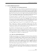
DIAMETER - 6.14 INCH (156 MM)
DEPTH - 1.05 INCH (27 MM)
7.26 INCHES
(184 MM)
3.88 INCHES
(99 MM)
2.26 INCHES
(57 MM)
7.90 INCHES
(201 MM)
2.38 INCHES
(60 MM)
8.65 INCHES
(220 MM)
4 dBi GAIN CEILING-MOUNT
HALLWAY
2.5 dBi GAIN CEILING-MOUNT
OMNIDIRECTIONAL
7.5 dBi GAIN
90 DEGREE DIRECTIONAL PANEL
(WALL/CORNER-MOUNT)
ALL ANTENNAS ARE EQUIPPED WITH
A 72-INCH RG58/U CABLE TERMINATED
WITH A MALE SMA CONNECTOR
MOUNTING STUD
LENGTH - 1.5 INCHES (38 mm)
DIAMETER - 0.875 INCHES (22 MM)
MOUNTING STUD
LENGTH - 1.5 INCHES (38 mm)
DIAMETER - 0.875 INCHES (22 MM)
18073-A
INCLUDES ADJUSTABLE
MOUNTING BRACKET
(NOT SHOWN)
Figure 12. 800 MHz DRU Antenna Options
3.8 External Alarm System Reporting Requirements
The DHU provides normally open (NO) and normally closed (NC) form C dry alarm relay
contacts for reporting minor and major alarms to an external alarm system. A minor alarm is
defined as a high temperature condition. A major alarm is defined as any fault condition
except high temperature. Connections to the alarm contacts are provided through a screw-type
terminal strip. Category 3 or 5 cable should be used for the alarm wires. If an external alarm
system is not in use, no alarm connections are required.
3.9 Maintenance Requirements
The Digivance ICS requires no regular maintenance to insure continuous and satisfactory operation.
Maintenance, as it applies to the Digivance ICS, primarily involves diagnosing and correcting
service problems as they occur. Faults and failures arising from within the Digivance ICS will
generate an external alarm response which includes lighting an LED indicator(s) and closing or
opening a set of alarm contacts. When an alarm is reported, it will be necessary to isolate the source
of the problem by observing the LED indicators on each unit and then performing various tests to