
User's Manual
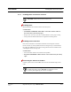
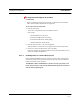
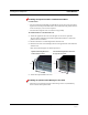
Table Of Contents
- SECTION 1 General Information
- SECTION 2 InterReach™ Unison System Description
- SECTION 3 Unison Main Hub
- SECTION 4 Unison Expansion Hub
- SECTION 5 Unison Remote Access Unit
- SECTION 6 Installing Unison Components
- 6.1 Installation Requirements
- 6.2 Safety Precautions
- 6.3 Preparing for System Installation
- 6.4 Unison Component Installation Procedures
- 6.5 Starting and Configuring the System
- 6.6 Interfacing a Main Hub to a Base Station or Roof-top Antenna
- 6.7 Connecting Contact Alarms to a Unison System
- SECTION 7 Installing and Using the AdminManager Software
- SECTION 8 Designing a Unison Solution
- 8.1 Maximum Output Power per Carrier at RAU
- 8.2 Estimating RF Coverage
- 8.3 System Gain
- 8.4 Link Budget Analysis
- 8.4.1 Elements of a Link Budget for Narrowband Standards
- 8.4.2 Narrowband Link Budget Analysis for a Microcell Application
- 8.4.3 Elements of a Link Budget for CDMA Standards
- 8.4.4 Spread Spectrum Link Budget Analysis for a Microcell Application
- 8.4.5 Considerations for Re-Radiation (over-the-air) Systems
- 8.5 Optical Power Budget
- 8.6 Connecting a Main Hub to a Base Station
- 8.7 Designing for a Neutral Host System
- SECTION 9 Replacing Unison Components in an Operating System
- SECTION 10 Maintenance, Troubleshooting, and Technical Assistance
- APPENDIX A Cables and Connectors
- APPENDIX B Compliance
- APPENDIX C Glossary

Installing Unison Components PRELIMINARY
6-12 InterReach Unison User Guide and Reference Manual
PN 8700-10
620003-0
Testing and Connecting the ScTP Cable
Consideration:
• Before connecting the ScTP cable to the RAU, confirm that it meets TIA/EIA
568-A standard and the TIA/EIA/IS-729 supplement.
To test and connect the ScTP cable:
1. Perform cable testing.
Test results are required for the final As-Built Document.
Cable length:
– Absolute Minimum: 10 m (33 ft)
– Recommended Minimum: 25 m (82 ft)
– Recommended Maximum: 100 m (328 ft)
– Absolute Maximum: 150 m (492 ft)
2. Label the cable and make a note of the designation.
This information is needed when connecting the cable to the Expansion Hub.
3. Connect the cable to the RJ-45 female port on the RAU.
Power is supplied by the Expansion Hub. Because the Expansion Hub is not yet
connected, no LEDs will illuminate.
6.4.1.1 Installing RAUs in a Neutral Host System
When installing both iDEN and cellular systems in parallel, either as dual-band or
neutral host systems, special provision must be taken to assure that the individual
RAUs do not interfere with each other.
The 800 MHz cellular and iDEN RAU’s antennas must be separated by 6 to 8
meters (20 to 26 feet) to assure that the iDEN downlink signals do not interfere
with the cellular uplink signals.