
User's Manual
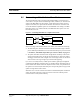

Table Of Contents
- SECTION 1 General Information
- SECTION 2 InterReach™ Unison System Description
- SECTION 3 Unison Main Hub
- SECTION 4 Unison Expansion Hub
- SECTION 5 Unison Remote Access Unit
- SECTION 6 Installing Unison Components
- 6.1 Installation Requirements
- 6.2 Safety Precautions
- 6.3 Preparing for System Installation
- 6.4 Unison Component Installation Procedures
- 6.5 Starting and Configuring the System
- 6.6 Interfacing a Main Hub to a Base Station or Roof-top Antenna
- 6.7 Connecting Contact Alarms to a Unison System
- SECTION 7 Installing and Using the AdminManager Software
- SECTION 8 Designing a Unison Solution
- 8.1 Maximum Output Power per Carrier at RAU
- 8.2 Estimating RF Coverage
- 8.3 System Gain
- 8.4 Link Budget Analysis
- 8.4.1 Elements of a Link Budget for Narrowband Standards
- 8.4.2 Narrowband Link Budget Analysis for a Microcell Application
- 8.4.3 Elements of a Link Budget for CDMA Standards
- 8.4.4 Spread Spectrum Link Budget Analysis for a Microcell Application
- 8.4.5 Considerations for Re-Radiation (over-the-air) Systems
- 8.5 Optical Power Budget
- 8.6 Connecting a Main Hub to a Base Station
- 8.7 Designing for a Neutral Host System
- SECTION 9 Replacing Unison Components in an Operating System
- SECTION 10 Maintenance, Troubleshooting, and Technical Assistance
- APPENDIX A Cables and Connectors
- APPENDIX B Compliance
- APPENDIX C Glossary

PN 8700-10 Help Hot Line (U.S. only): 1-800-530-9960 9-3
620003-0
PRELIMINARY Replacing an Expansion Hub
9.2 Replacing an Expansion Hub
Replacing an Expansion Hub
1. Turn off the power to the Expansion Hub.
2. Disconnect all Cat-5/6 cables, both fiber cables, and the AC power cord.
3. Replace the Expansion Hub with a new one.
4. Connect the AC power cord, all Cat-5/6 cables, and both fiber cables – remember-
ing to clean and correctly connect the uplink and downlink fiber.
5. Turn on the power to the Expansion Hub.
AdminManager Tasks
• The Main Hub automatically issues the band setting.
• When convenient, perform System Test to optimize performance.
During System Test, the entire system is temporarily off-line and no RF is
being transmitted.
Checking the Expansion Hub’s LEDs
• The LEDs should blink through all states on power up.
• If the LEDs do not blink on power up, replace the Expansion Hub.
• If the LEDs do not illuminate at all, make sure the AC power cable is con-
nected.
•The
UL STATUS and DL STATUS LEDs should be green.
•The
E-HUB STATUS and POWER LEDs should be green.
• For each RJ-45 port that has an RAU connected:
•The
E-HUB/RAU LEDs should be green.
•The
LINK LEDs should be green.
It can take several seconds for each Cat-5/6 connection for the LEDs to display
properly.
NOTE: Refer to Section 10 for troubleshooting using the LEDs.