
User's Manual
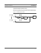
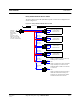


Table Of Contents
- SECTION 1 General Information
- SECTION 2 InterReach™ Unison System Description
- SECTION 3 Unison Main Hub
- SECTION 4 Unison Expansion Hub
- SECTION 5 Unison Remote Access Unit
- SECTION 6 Installing Unison Components
- 6.1 Installation Requirements
- 6.2 Safety Precautions
- 6.3 Preparing for System Installation
- 6.4 Unison Component Installation Procedures
- 6.5 Starting and Configuring the System
- 6.6 Interfacing a Main Hub to a Base Station or Roof-top Antenna
- 6.7 Connecting Contact Alarms to a Unison System
- SECTION 7 Installing and Using the AdminManager Software
- SECTION 8 Designing a Unison Solution
- 8.1 Maximum Output Power per Carrier at RAU
- 8.2 Estimating RF Coverage
- 8.3 System Gain
- 8.4 Link Budget Analysis
- 8.4.1 Elements of a Link Budget for Narrowband Standards
- 8.4.2 Narrowband Link Budget Analysis for a Microcell Application
- 8.4.3 Elements of a Link Budget for CDMA Standards
- 8.4.4 Spread Spectrum Link Budget Analysis for a Microcell Application
- 8.4.5 Considerations for Re-Radiation (over-the-air) Systems
- 8.5 Optical Power Budget
- 8.6 Connecting a Main Hub to a Base Station
- 8.7 Designing for a Neutral Host System
- SECTION 9 Replacing Unison Components in an Operating System
- SECTION 10 Maintenance, Troubleshooting, and Technical Assistance
- APPENDIX A Cables and Connectors
- APPENDIX B Compliance
- APPENDIX C Glossary

PN 8700-10 Help Hot Line (U.S. only): 1-800-530-9960 6-37
620003-0
PRELIMINARY Alarm Source
Daisy-Chained Alarm Source Cable
The daisy-chained alarm cable (PN 300117-0) that is used in these configurations is
shown in Figure 6-8.
Figure 6-8 Daisy-Chained Alarm Source Cable
1 meter (3 feet)
Pins 7 and 9
J2
LGCell, MetroReach Focus,
or Unison Alarm
DB-9 female Port
Pin 7
Pin 9
X
J3
Pin 7
Pin 9
X
J4
Pin 7
Pin 9
X
J5
Pin 7
Pin 9
X
J6J7
DB-9 male
Pins 7 and 9
DB-9 male
Pins 7 and 9
DB-9 male
Pins 7 and 9
DB-9 male
Pins 7 and 9
DB-9 male
Pin 7
DB-9 female
J1
DB-9 male
7
9
Pin 7
Pin 7
Option 1: Connect 5 units to cable using
J2 through J6; J7 is unused.
OR
Option 2: Connect four units to first cable
using J2 through J5, connect J6 to an
additional 300117-0 cable’s J1 connector;
J7 is unused.
OR
Option 3: Connect less than four units to
cable and terminate the circuit by con-
necting the J7 connector into the lowest
numbered unused male connector.
Pin 9
LGCell, MetroReach Focus,
or Unison Alarm
DB-9 female Port
LGCell, MetroReach Focus,
or Unison Alarm
DB-9 female Port
LGCell, MetroReach Focus,
or Unison Alarm
DB-9 female Port
to Unison,
Base Station,
or MetroReach
Focus
(use male-to-male
adapter, included with
cable, when connecting
to Unison or MetroReach)