2 LGCell Equipment This section describes the LGCell equipment and explains how the system operates and contains LGCell system specifications. For details about cables and connectors, refer to Appendix A – Cables, Connectors, and Accessories. LGCell has no user-serviceable parts. Faulty or failed units may be repaired or replaced through LGC Wireless. In the U.S., please contact us at 1-800-530-9960. International customers, please contact us at +1-408-487-2400.
-2 LGCell Equipment
Standard Equipment The LGCell standard equipment supports 800 MHz AMPS/TDMA/CDMA/iDEN, 900 MHz GSM, 1800 MHz DCS, 1800 MHz Korean PCS, 1900 MHz TDMA/ CDMA/GSM, and Dual Band 900 GSM/1800 DCS installations.
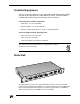
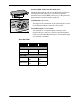
The Main Hub also receives signals from the Expansion Hubs and reconverts them back to the cellular or PCS band for transmission on the uplink channel (mobile) to the macrocellular base station (BTS) or microcellular base station (MBS). The Dual Band 900/1800 Main Hub is shown below. Main Hub Features 2-4 • Mounts in a standard 19” equipment rack, width 17.25” (438 mm) • Height is 1.7” (44.5 mm). The Dual Band Main Hub is 3.5” (88.9 mm) high. • Operates with worldwide AC power, 100-240 VAC at 1.
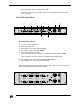
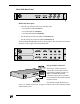
• Displays system status via front panel LEDs • Provides contact closure of major alarms and error latches through a D-sub 9-pin connector Main Hub Front Panel 5 5 5 1 6 5 3 7 4 2 Front Panel Description 1 AC power cord connector 2 Power On/Off switch 3 One LED for sync status (labeled SYNC) 4 One LED for power (labeled POWER) 5 Four Ports (labeled 1, 2, 3, 4) •One standard female ST-connector for MMF downlink (labeled DOWN) •One standard female ST-connector for MMF uplink (labeled UP) 6 One L
Standard MMF Uplink and Downlink Ports The Main Hub transmits and receives RF signals to and from the Expansion Hubs using up to 1 kilometer of industrystandard 62.5µm/125µm MMF cable (up to 1.5 dB optical loss, approximately 1 kilometer without jumpers). •Uplink/Input (labeled UP) This signal is the combination of all uplink signals received by the Expansion Hubs connected to the system.
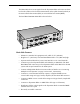
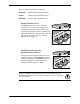
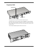
Main Hub Back Panel Back Panel Description • Three N-type, Female Connectors with dust caps • One Duplexed (labeled DUPLEX) • One Uplink (labeled REVERSE) • One Downlink (labeled FORWARD) • One D-Sub 9-pin Connector (labeled DIAGNOSTIC 1) • One D-sub 25-pin Connector (labeled DIAGNOSTIC 2) The Dual Band Main Hub Back Panel is shown below. The connectors are the same as shown for the single band LGCell Main Hub.
There are three N-type female connectors: Duplexed: Output and Input (bi-directional) Uplink: Simplex Output (unidirectional) Downlink: Simplex Input (unidirectional) • Duplexed (labeled DUPLEX) The DUPLEX connector is for a duplexed connection. This connector provides both downlink and uplink signals to and from the roof-mounted antenna, repeater, or MBS to the Main Hub. This duplex port provides a 30 or 40 dB gain on the duplex part. See “LGCell System Gain” on page 17.
D-Sub 9-Pin Connector The D-Sub 9-pin connector (labeled DIAGNOSTIC 1) provides contact closure for major and latch system alarm monitoring. The following table lists the function of each pin on the D-sub 9-pin connector.
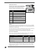
Expansion Hub Antenna Ports Main Hub Port 1 2 3 4 The Expansion Hub is LGCell’s intermediate distribution point. It transmits and receives low frequency signal (<200MHz) to and from the Main Hub, and to and from the RAUs. Utilizing LGC Wireless’ proprietary technology, both the MMF and the UTP/STP cables can transmit signals in the cellular or PCS frequency bands.
Expansion Hub Features • Mounts in a standard 19" equipment rack, with 17.25” (438 mm) • Height is 1.7" (44.5 mm). The Dual Band Expansion Hub is 3.5” (88.9 mm) high. • Operates with worldwide AC power, 100-240 VAC at 1.6 A and 50/60 Hz • Connects up to four RAUs. The Dual Band Expansion Hub connects up to four RAUs for the 900 system and up to four RAUs for the 1800 system. • Connects to the Main Hub with MMF transmit/receive cable (up to 1.
8 One LED to monitor RF link status (labeled LINK STATUS) 9 One LED to monitor sync status (labeled SYNC) The Dual Band Expansion Hub Front Panel is shown below. The connectors are the same as those explained for the single band system. 900 MHz DUAL BAND 1800 MHz Standard MMF Uplink and Downlink Port The Expansion Hub transmits and receives cellular or PCS signals to and from the Main Hub using up to 1 kilometer of industrystandard 62.5µm/125 µm MMF cable found in most buildings.
UTP/STP CAT 5 Cable Connectors Delivers electrical power to the RAUs. Also transmits downlink signals and receives uplink signals to and from the RAUs.
The Dual Band 900/1800 RAU is shown here. The Dual Band RAU has the same connectors as the single band RAU. It has one set of connectors for the 900 RAU and one set for the 1800 RAU. RAUs are active antennas that connect directly to an Expansion Hub over standard CAT 5 (or better) UTP/STP cable. The cable also delivers electrical power to the antenna. RAUs receive uplink cellular or PCS signals and re-transmits them to an Expansion Hub in a low frequency signal format (<200MHz).
RAU Connectors SMA Connector The SMA connector on the RAU is a duplexed RF input/output port that connects to standard in-building antennas. •Uplink (Input) The uplink cellular or PCS channels are received from the mobile phone by the in-building antenna. For the maximum downlink composite radiated power at the RAU, see the table on page 17 in this chapter. •Downlink (Output) The downlink channels are transmitted (radiated) by the standard in-building antenna.
RAU Optional Antennas The following illustration shows optional antennas that can plug into the SMA connector. For recommended antennas, refer to the accessory section in the LGCell Price List or contact your account manager. LGCell System Specifications The following tables give system specifications for LGCell. 2-16 • System gain, maximum input/output RF Power • Maximum Input Power per Carrier vs.
LGCell System Gain This table is a summary of the system gain for different frequencies and formats. System Gain LGCell Frequency/Format Duplex Simplex 800 MHz AMPS, TDMA 30 0 800 MHz CDMA 30 0 800 MHz iDEN 0 0 900 MHz GSM 0 0 1800 MHz CDMA 0 0 DCS 1800 GSM 0 0 1900 MHz TDMA 40 0 1900 MHz CDMA 40 0 1900 MHz GSM 40 0 Maximum Input RF Power per Carrier vs.
800 AMPS Number of Carriers 800 TDMA Maximum Maximum Power Composite per Power Carrier Number of Carriers 800 GSM Maximum Maximum Power Composite per Power Carrier Number of Carriers Maximum Maximum Power Composite per Power Carrier 1 20.0 20.0 1 17.0 17.0 1 20.0 20.0 2 15.5 18.5 2 12.5 15.5 2 8.0 11.0 3 12.8 17.6 3 9.8 14.6 3 6.0 10.8 4 11.0 17.0 4 8.0 14.0 4 4.7 10.7 5 9.5 16.5 5 6.5 13.5 5 3.8 10.8 6 8.3 16.1 6 5.3 13.1 6 3.0 10.8 7 7.3 15.
1800 DCS/GSM Number of Carriers 1900 AMPS Maximum Maximum Power Composite per Power Carrier Number of Carriers 1900 TDMA Maximum Maximum Power Composite per Power Carrier Number of Carriers Maximum Maximum Power Composite per Power Carrier 1 18.0 18.0 1 20.0 20.0 1 17.0 17.0 2 6.0 9.0 2 13.5 16.5 2 12.5 15.5 3 4.0 8.8 3 11.5 16.3 3 9.8 14.6 4 2.7 8.7 4 10.3 16.3 4 8.0 14.0 5 1.8 8.8 5 9.3 16.3 5 6.5 13.5 6 1.0 8.8 6 8.3 16.1 6 5.3 13.1 7 0.3 8.
1900 GSM Number of Carriers Maximum Power per Carrier Maximum Composite Power 1 20.0 20.0 2 8.0 11.0 3 6.0 10.8 4 4.7 10.7 5 3.8 10.8 6 3.0 10.8 7 2.3 10.8 8 2.0 11.0 9 1.5 11.0 10 1.2 11.2 11 0.8 11.2 12 0.5 11.3 13 0.3 11.4 14 0.0 11.5 15 -0.1 11.7 16 -0.3 11.7 Band Selective Option LGCell 800 MHz, 900 MHz, 1800 MHz, and 1900 MHz The LGCell 800/900 MHz system has fixed bands of operation.
The following table shows the bandwidths for each type of system. System DAS 800 MHz - AMPS, Fixed Filter Bandwidth Uplink Center Frequency Downlink Center Frequency 25 MHz 836.5 MHz 881.5 MHz DAS 800 MHz - iDEN 18 MHz 815 MHz 860 MHz DAS 900 GSM 25 MHz 947.5 MHz 902.5 MHz DAS 1800 KOREAN CDMA 30 Mhz 1765 MHz 1855 MHz DAS 1800 DCS (GSM) 30 MHz 1725 MHz1 to 1770 MHz 1820 MHz1 to 1865 MHz DAS 1900 MHz - CDMA, 15 MHz 1857.5 MHz2 to 1892.5 MHz 1937.5 MHz2 to 1972.
Band Center Frequency of the DCS 1800 MHz LGCell The filter band is 30 MHz wide (or 15 MHz on each side of the center). Uplink Freq Downlink Freq Uplink Freq Downlink Freq 1725.00 1820.00 1748.75 1843.75 1726.25 1821.25 1750.00 1845.00 1727.50 1822.50 1751.25 1846.25 1728.75 1823.75 1752.50 1847.50 1730.00 1825.00 1753.75 1848.75 1731.25 1826.25 1755.00 1850.00 1732.50 1827.50 1756.25 1851.25 1733.75 1828.75 1757.50 1852.50 1735.00 1830.00 1758.75 1853.75 1736.
3 LGCell Site Planning and Design This section provides information to assist in planning and designing an LGCell system and preparing a site for the LGCell installation. Proper project management is instrumental in providing a timely and accurate deployment. The first step in planning an LGCell system is to estimate the amount of radio frequency (RF) coverage you need for your building or coverage area. Initial estimates can be developed using floor plans and the models that follow.
3-2 LGCell Site Planning and Design
Project Management Installing the LGCell system is easy after all of the pre-installation requirements are met. It is beneficial to have one person manage and coordinate all aspects of the planning, design, and installation. Managing the process should avoid unnecessary surprises. The project manager is the person responsible for assigning tasks and ensuring scheduled work is performed on time.
Project Management Estimated Timeline Description Details Time Interval Detailed site walkthrough/RF survey Prepare installation information, including RF plan, floor plan, equipment order form, and final design. 2 weeks Order LGCell equipment Get all standard parts and accessories required. 8 weeks Select cabling contractor Complete installation statement of work and provide floor plan with equipment locations, list of cabling runs, and other materials and connections.
Antenna Coverage for 800/900 MHz Frequency Applications (0 dBm per carrier, 5 dB fade margin, -85 dBm design goal and 3 dBi antenna gain) Facility PLS Coverage per Antenna (Square Feet) Manufacturing 27.3 30,000 Hospital 28.8 15,000 Airport 27.3 30,000 Retail 27.7 25,000 Warehouse 27.3 30,000 Parking Garage 26.8 40,000 Antenna Coverage for 1800/1900 MHz Frequency Applications Facility PLS Coverage per Antenna (Square Feet) Manufacturing 24.9 25,000 Hospital 26.
Office Antenna Coverage for 1800/1900 MHz Frequency Applications Facility PLS Coverage per Antenna (Square Feet) Open - 80% cubicles/20% offices 25.2 20,000 80% - 50% cubicles/50% offices 25.7 15,000 10% - 20% cubicles/80% offices 26.5 10,000 The preceding tables show estimated clutter-defined path loss slope (PLS) for different frequencies at various kinds of sites. If you change the design goal or other parameters, these numbers will change based on the PLS.
As a reference the following table gives estimates of the signal loss for some RF barriers. Average Signal Loss of Common Building Materials Partition Type Loss @ 815 MHz Metal wall 26 dB Aluminum siding 20 dB Concrete block wall 13 dB Foil insulation 4 dB Concrete floor 15 dB Sheetrock 1.4 dB RF Measurements and Site Survey Before designing an LGCell system, one should go to the site and measure the loss characteristics of the building.
Site Survey Questionaire 585 EAST BROKAW ROAD | SAN JOSE, CA 95112 | TEL 408.487.2400 | FAX 408.487.