
User's Manual
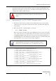


Table Of Contents
- UltraWAVE Micro BTS Installation and Commissioning Guide
- Chapter 1 - Unpacking and Configuration Verification
- Chapter 2 - Installation
- 2.1 Analyzing Site Requirements
- 2.2 Mounting the Micro BTS Chassis
- 2.3 Configuring the E1 or T1 Trunk Card
- 2.4 Connecting Ground Cables
- 2.5 Connecting Power Supplies
- 2.6 Connecting E1 or T1 Trunk Cables
- 2.7 Connecting Antennas
- 2.8 Connecting External Alarms
- 2.9 Making a Serial Connection to the Processor Card
- 2.10 Network Connections
- 2.11 Post Installation Cabling and Checks
- Chapter 3 - Off-Line Commissioning
- 3.1 Pre Off-Line Commissioning
- 3.2 Off-Line Commissioning of the Micro BTS
- 3.2.1 Starting XWindows Using the Craft PC
- 3.2.2 Connecting the Craft PC to the ICP Processor Card
- 3.2.3 Setting Up a Serial Connection via the ICP Processor Card Serial Port
- 3.2.4 Power-On LED Tests
- 3.2.5 Configuring Boot Parameters
- 3.2.6 Setting Up an Ethernet Connection to the ICP Processor Card Ethernet Port
- 3.2.7 Verifying Telnet Communications with the Micro BTS over Ethernet
- 3.3 Software Verification using Craft PC
- 3.3.1 Verifying the Current Software Version and Patch Level
- 3.3.2 Checking the Flash Version Number
- 3.3.3 Running E1 or T1 POST Diagnostics
- 3.3.4 Running TRX POST Diagnostics
- 3.3.5 Reviewing POST Results
- 3.3.6 Rebooting the Micro BTS after Running POST
- 3.3.7 Terminating Serial Communications with the Micro BTS
- 3.3.8 Exiting XWindows on the Craft PC
- 3.4 Upgrading the Micro BTS Software Version (Flash)
- 3.5 Post Off-Line Commissioning
- Chapter 4 - Off-Line Commissioning of a Daisy Chain
- Chapter 5 - On-Line Commissioning
- Checklist 1 - Site Readiness Checklist
- Checklist 2 - Installation Checklist
- Checklist 3 - Commissioning Checklist
- Index

UltraWAVE Micro BTS Installation and Commissioning Guide, Version B 85
Software Verification using Craft PC
The flash version number should be iw07_00.012 or higher for BTS TRX POST
diagnostics to be able to run. If it is not, the flash version number will have to be
changed and the Micro BTS rebooted.
3.3.3 Running E1 or T1 POST Diagnostics
1 Disconnect all E1 and/or T1 lines from the BTS. This ensures that no Abis
connection exists. If an Abis connection does exist, the TRX POST might not
run properly.
2 Wait until the bts-> prompt appears, and type:
bts-> reboot [ENTER]
This action reboots the Micro BTS. The VxWorks kernel is started, several E1
or T1 trunk card tests run sequentially, and the results of each test are listed
as PASSED/FAILED. Only if all seven tests passed successfully will the E1 or
T1 POST diagnostics be considered successful. The E1 or T1 POST results will
be displayed after the boot process has been completed.
Flash Image 2 is reserved for Alvarion Customer Service use
ONLY.
The coding for the E1 or T1 trunk card, its modules and scripts
generically refer to the E1 or T1 trunk card objects as “E1”,
whether the corresponding ports are configured as E1 or T1.
1 (e1diag) E1 CARD in SLOT 1: STARTING POST/OFFLINE Test
2 (e1diag) testsPtr 0xffb33ab4 testsPtr[0] 0x5
3 (e1diag) testsPtr 0xffb33ab4 testsPtr[0] 0x5 result 0x0 i 1
4 (e1diag) E1(1) TID01: Initialize Peripheral Registers: PASSED
5 (e1diag) testsPtr 0xffb33ab4 testsPtr[0] 0x5 result 0x0 i 2
6 (e1diag) E1(1) TID02: Peripheral Register Test: PASSED
7 (e1diag) testsPtr 0xffb33ab4 testsPtr[0] 0x5 result 0x0 i 3
8 (e1diag) E1(1) TID03: Framer Register Test: PASSED
9 (e1diag) testsPtr 0xffb33ab4 testsPtr[0] 0x5 result 0x0 i 4
10 (e1diag) E1(1) TID04: VME to CPU FIFO Flag Test: PASSED
11 (e1diag) testsPtr 0xffb33ab4 testsPtr[0] 0x5 result 0x0 i 5
12 (e1diag) E1(1) TID05: Initialize Time/Space sw Chip: PASSED
13 (e1diag) testsPtr 0xffb33ab4 testsPtr[0] 0x5 i 6
14 (e1diag) E1 CARD in SLOT 1: COMPLETED POST/OFFLINE Test: PASSED
Figure 3-8: E1 or T1 POST Results