
Installation Instructions

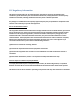
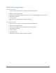
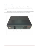
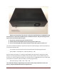
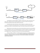
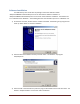
Table Of Contents
6
ACRS 1.0
Base Radio
Feed Cable
Antenna
Base Control
PC
Ethernet
Internet
Ethernet
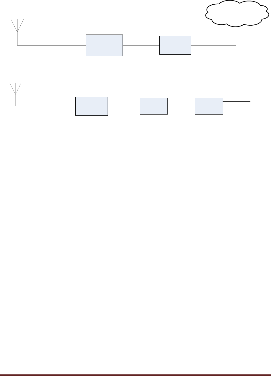
Base station installation diagram.
ACRS 1.0
Client Radio
Feed Cable
Antenna
Client Control
PC
Ethernet
Broadband
Router
Ethernet
Ethernet/WiFi
Client
Devices
Client station installation diagram.
The above figures show the hardware installations at both the base station side and the client
station side to allow the client side networking devices to connect to the Internet through the TV
whitespace link between the base station and the client station.
For both the base station and the client station installations, the ACRS 1.0 radio N-type
connector is connected to the feed cable which is connected to the antenna. The Ethernet ports of the
base and client radios are connected to Ethernet ports on the base control PC and client control PC.
Both the base control PC and the client control PC have dual Ethernet ports. One of the Ethernet
port is connected to the radio. The second Ethernet port on the base control PC is connected to a router
or switch that connects to the Internet. The second Ethernet port on the client control PC is connected
to a broadband router or switch which connects to the client side networking devices.
Once the hardware installation is complete, follow the instructions in the following sections to
perform the software installation on the control PC. Note if an installed radio unit and control PC are
redeployed at a differently location, the installer must uninstall the old software and reinstall the
software on the control PC.