
Car Speaker User Manual


7
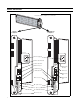
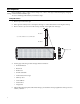
Bank 1 and Bank 2 DIP switches
Bank 1 DIP switches Bank 2 DIP switches
12345678910 12345678910
DIP switch 1
DIP switch 2
Switches 3, 4, 5: Baud rates
ON
Switch 8: Data format
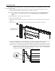
Switches 1, 2: EOL termination
Switch 6: RS485 echo (See page 8.)
Switch 7: IR Remote disabled
Switch 10: Memory clear
Switches 9, 10: Diagnostics
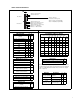
Switches 1 through 7:
Serial address in binary format.
Switch 1 = LSB (Least Significant Bit)
Switch 7 = MSB (Most Significant Bit).
Switch 9: Demonstration messages
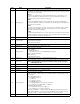
EOL termination 1 2
Set end-of-line termination off
(default)
00
Set end-of-line termination on 1 1
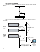
Baud rate 3 4 5
9600 (default) 0 0 0
1200 1 0 0
2400 0 1 0
4800 1 1 0
9600 0 0 1
19200 1 0 1
38400 0 1 1
9600 1 1 1
RS485 echo (See page 8.) 6
Disable RS485 echo (default) 0
Enable RS485 echo 1
IR remote disable 7
IR remote control can be used to change
a sign’s parameters (default)
0
IR remote control can not be used to
change a sign’s parameters
1
Demonstration messages 9
Enable demo messages (default) 0
Disable demo messages 1
Memory clear 10
Do not clear messages at power-up
(default))
0
Clear all messages at power-up 1
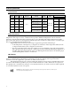
Note: For Ethernet, when you change the Data format using DIP switches,
a similar change must be made to the Data format of the internal Ethernet
card. (See “Setting Baud rate and Data format on an Ethernet-equipped
sign” on page 19.)
Serial Address (address 0 = default)
LSB = Least Significant Bit; MSB = Most Significant Bit
Dec Hex
1
LSB
23456 7
MSB
000000000 0
101100000 0
202010000 0
303110000 0
.
.
.
.
.
.
.
.
.
.
.
.
.
.
.
.
.
.
.
.
.
.
.
.
.
.
.
125 7D 1 01111 1
126 7E 0 11111 1
127 7F 1 11111 1
Data format 8
8N1 = 8 data bits, no parity, 1 stop bit. (default) 0
7E2 = 7 data bits, even parity, 2 stop bits 1
Diagnostic Description 9 10
Run normal
messages (default)
Normal messaging
enabled.
00
Test pattern Test for unlit LEDs. 1 0
LED test mode Test for dim LEDs. 0 1
Serial
troubleshooting
Contact Adaptive®
Technical Support.
11