PCM-3420 PC/104 Fast SCSI-2 Module
Copyright Notice This document is copyrighted, 1997. All rights are reserved. The original manufacturer reserves the right to make improvements to the products described in this manual at any time without notice. No part of this manual may be reproduced , copied , translated or transmitted in any form or by any means without the prior written permission of the original manufacturer. Information provided in this manual is intended to be accurate and reliable .
Packing Set Before you begin installing PCM-3420 Module, please make sure that the following materials have been shipped : - 1 PCM-3420 Fast SCSI-2 Host Adapter Module - SCSI-2 Flat Cable (50 Pin) - 1 PCM-3420 User's Manual - 1 EZ-SCSI LITE utility disk for Windows - 1 Manager Set utility disk for OS/2, Windows NT, Windows 95, and Netware v3.1x, v4.
or sales representative immediately. Contents Chapter 1 General Information ............. 1 Product Highlights ................................................................ 2 Introduction ........................................................................... 2 Features ................................................................................. 3 Peripheral Device Support .................................................. 3 Specifications .......................................................
SCSI Device Troubleshooting ............................................... 22 Windows 95/Windows NT Troubleshooting .......................... 22 Information for DOS/Windows 3.1x users ...................... 26 Appendix A Installing PC/104 Modules 31 Appendix B Pin Assignments ............... 35 PC/104 connectors .................................................................. 36 SCSI Hard Drive Connector ...................................................
CHAPTER General Information 1 This chapter gives background information on the PCM-3420.
Product Highlights l PC/104 Embedded-PC Module l SCSI-2 Compatibility l Optimized performance for DOS and Windows; support for all major operating systems l Customer configuration to match specific requirements l Economical connection of up to seven(7) SCSI devices l Proven Adaptec quality and reliability Introduction The PCM-3420 host adapter offers a wide range of flexible, economical and expandable solutions that can satisfy diverse needs in SCSI connectivity.
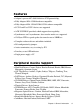
Features l Adaptec’s proven AIC-6360 16-bit fast SCSI protocol chip. l Fully Adaptec AHA-1520A hardware compatible. l Fully Adaptec AHA-1510A/1520A/1522A software compatible. l SCSI-2 and Fast SCSI-2 devices are supported. l ASW SCSI BIOS provided, which supports boot capability. l Synchronous and Asynchronous data transfer modes are supported. l 128 Bytes FIFO to speed up the data transfer rate to 10MB/sec. l Complete software drivers and utilities included. l I/O configuration by jumpers.
l Scanners: Cannon, Hewlett-Packard, Panasonic, Ricoh. The PCM-3420 is designed to be compatible with devices that comply with SCSI-2 standard, including those not on this list. Not all models from a given manufacturer have been tested. Specifications Technical Specifications Computer BUS: PC/104 (ISA) Standard Interface Protocol: PIO Device Protocol: SCSI-2 Fast SCSI Transfer Rate: Up to 10.
Board layout AIC-6360 Chapter 1 General Information 5
6 PCM-3420 User's Manual
CHAPTER Hardware Installation 2 This chapter tells how to set up the PCM3420 hardware , including instructions on setting jumpers and connecting SCSI devices. Be sure to read all the safety precautions before you begin the installation procedure.
Jumpers and Connectors Connectors on the board link it to SCSI devices and other PC/104 modules. In addition, the board has a number of jumpers that allow you to configure the SCSI application to suit your systems.
CN1 JP6 Operation Mode JP1 LED JP7 Port Addr. JP2 Termination Select SCSI-2 CN1 AIC-6360 JP8 BIOS Addr. SCSI-2 connector JP9 BIOS Addr. JP10 BIOS Func.
Locating Jumpers & Connectors Setting Jumpers You configure your PCM-3420 card to match the needs of your application by setting jumpers. Jumpers are the simplest kind of electric switch. They consist of two metal pins and a small metal clip (often protected by a plastic cover) that slides over the pins to connect them. To close” a jumper you connect the pins with the clip. To open a jumper you remove the clip. Sometimes a jumper will have 3 connect either three pins, labeled 1, 2, and 3.
Generally, you simply need a standard cable to make most connecWarning ! tions. Safety Precautions Caution ! Always completely disconnect the power cord from your chassis whenever you are working on it. Do not make connections while the power is on because sensitive electronic components can be damaged by the sudden rush of power . Only experienced electronics personnel should open the PC chassis. Always ground yourself to remove any static charge before touching the card.
Data Transfer Mode Programmed I/O SCSI Floppy/Floptical Disabled l Fast SCSI Disabled l > 1 Gbyte Translation Disabled In most cases, you will not need to change these settings. l l Jumper Configuration Reference Nine jumper blocks on the PCM-3420 host adapter are used to configure user-selectable options. The following description shows the proper jumper settings for their respective applications. Jumper Block JP2 : This jumper is used to set the terminator installed or uninstalled.
Jumper Block JP4 : This jumper block is used to set IRQ channel. You must also set the corresponding IC jumper on jumper block 5. Set IRQ 12 Set IRQ 11 * Set IRQ 10 Set IRQ 9 = Jumper 12 Close , Others Open = Jumper 11 Close , Others Open = Jumper 10 Close , Others Open = Jumper 9 Close , Others Open (Not recommended with Windows 3.
10 Open Close (JP4/IRQ10 also set close) 11 * Close Open (JP4/IRQ11 also set close) 12 Open Open (JP4/IRQ12 also set close) (* means default setting) Jumper Block JP4 also needs to set to the same IRQ channel. JP5 Set PCM-3420 DMA Channel : This setting is valid only if DMA is enabled on JP6 (DT - data transfer mode).
Parity Checking SP Enabled * Close Disabled Open (* means default setting) Jumper Block JP6 : This jumper block provides six major PCM-3420 operation mode settings , including data transfer mode, booting, fast SCSI , ..... etc.
R1 Enable/Disable greater than 1 GB Translation > 1 Gbyte Translation On = Open > 1 Gbyte Translation Off* = Close (* means default setting) Jumper Block JP7 : If JP10 BIOS setting is enabled , you should use this jumper to assign a Port address. Port 340h * = 2-3 Close Port 140h = 1-2 Close (* means default setting) Notes : The PCM-3420 host adapter BIOS supports booting only for the default port address of 340h.
adapter BIOS is enable , you should assign a right BIOS address (JP8 and JP9) and port address (JP7) at the same time. Host Adapter BIOS Disabled Host Adapter BIOS Enabled* (* means default setting) = Open = Close SCSI Hard Disk Drive Connector (CN1) The SCSI hard disk drives require a 50-pin flat cable. Wire number 1 on the cable is red or blue, and the others wires are gray. 1.Connect one end of the cable to CN1.
18 PCM-3420 User's Manual
CHAPTER EZ-SCSI Quick Reference 3 Use this chapter to learn about Adaptec EZ-SCSI 4.0 : l l l l System Requirements Installation procedures Troubleshooting Information DOS Device Drivers and Formatting Utilities To learn about Adaptec EZ-SCSI Windows application , see their online help.
System Requirements for Full Installation l l l A 386-based PC or higher with at least 4Mbytes of memory , 10MBytes of free disk space , and a 3.5-inch floppy drive An ASPI-compliant SCSI host adapter (like PCM-3420) and a CD-ROM drive Microsoft Windows 95 , Windows NT version 3.51 or above , Windows 3.1x, Windows for Workgroups 3.1x, or DOS 6.x or above. Quick Start Instructions First, install your PCM-3420 host adapter and other SCSI devices (see chapter 2) .
Windows/Windows for Workgroups 3.1x 1.Install Windows 3.1x or Windows for Workgroups 3.1x and start it running on your computer. 2.Insert the EZ-SCSI Diskette in your floppy disk drive. 3.Select File/Run from the Program Manager menu. 4.When the Run dialog box appear, type a:\setup if you are using the A drive or b:\setup if you are using the B drive. Then click OK. 5.Following the instructions that appear on the screen. DOS 1.Install DOS 6.x or above ,and start it running on your computer. 2.
Troubleshooting Tips SCSI Device Troubleshooting Review this checklist if your newly-installed SCSI disk drivers , CDROM drivers, and other devices do not seem to work properly. l Be sure that termination setting are set correctly for all devices on the SCSI bus, as described in chapter 2. l Be sure there are no hardware conflicts, such as devices in your computer trying to use the same interrupts(IRQs) or DMA channels. l Be sure the cables connecting SCSI devices and the PCM-3420 are attached securely.
the model name of the host adapter does not appear under Device Manager? A:If the SCSI controllers icon or your host adapter's model name (AHA-152X, not PCM-3420) do not appear, open Control Panel and double-click the Add New Hardware icon. Let Windows search for the host adapter by selecting Yes on the second screen of the Add New Hardware Wizard.
the host adapter and other hardware in your computer. You can fix this zby changing the hardware resource settings. Q:What do I need to do if I change or upgrade my host adapter ? A: 1. Open the Control Panel, double-click on system, and click the Device Manager tab. 2. Double-click the SCSI Controllers icon, select the name of the old host adapter, and click remove. 3. Turn off the computer and physically remove the currently installed host adapter. 4. Turn the computer On.
the embedded Windows 95 CD-ROM driver. You can add support for the CD-ROM drive by doing the following : 1. Click the start button and select restart the computer in MS-DOS mode. 2. When the DOS prompt appears, follow the Quick Start instructions for DOS on previous page. 3. When you are finished running Adaptec EZ-SCSI for DOS, find the file named cdtsd.vxd in the Windows\system\iosubsys directory and rename it cdtsd.sav. Q:My CD-ROM drive shows up as more than one icon under my computer.
Information for DOS/Windows 3.1x Users The following information may be useful if you install EZ-SCSI on a computer running DOS, Windows 3.1x, or Windows for Workgroups 3.1x. DOS and Windows 3.1x Device Driver Devices drivers are software programs that enable your computer to communicate with SCSI devices such as hard disk drivers, CD-ROM drivers, and scanners. Each kind of device requires a different device driver. Adaptec EZ-SCSI includes several DOS/Windows 3.
Low-level Formatter (scsifmt) Use the DOS-based scsifmt utility for low-level formatting of SCSI hard disk drives, removable media, Floptical drivers, and magneto-optical drivers. You can also use it to scan a disk device for surface defects before you store data on it. Run scsifmt from the DOS prompt, not from the Windows MS-DOS prompt. Before you run it, be sure the disk devices you want to format are connected to the PCM-3420 host adapter and they are powered. Then follow these step : 1.
Formatter and Partitioner (afdisk) Use the DOS-based afdisk utility to partition and format SCSI hard disk drivers, Floptical drivers, and magneto-optical drivers. You can also use afdisk to remove DOS and non-DOS partitions from a disk drive and to format removable media in standard disk format, OS/2 floppy format, or DOS/V (Japanese) format. Note : Use afdisk only if the disk device is not controlled by the PCM-3420 host adapter BIOS - that is , if the PCM-3420’s BIOS is not enabled.
3.To create a new partition on the disk devices, press Ins. A screen will appear. The Create a DOS Partition window suggests that you create one partition on the disk device , equal to its entire capacity. If this is what you want to do , skip to step 5. 4.To change the size of partition, use the arrow keys to select Start Cylinder and End Cylinder, and type in the numbers you want. Partitions up to 2 Gigabytes are supported. 5.When the number of cylinder is what you want, press ESC.
DOS prompt and press Enter. A list of SCSI devices appears. (Device that support removable media are marked.) If your computer has two or more host adapter, you need to add another number to the command. For example, if you have two PCM3420 host adapters, one of them is host adapter 0 and the other is host adapter 1.
APPENDIX A Installing PC/104 Modules This appendix gives instructions for installing PC/104 Modules.
Installing PC/104 modules The CPU card's PC/104 connectors give you the flexibility to attach PC/104 expansion modules. These modules perform the functions of traditional plug-in expansion cards, but save space and valuable slots.
PC/104 Mounting Support Female Male PC/104 Module CPU Card PC/104 Module Mounting Diagram 3.500 3.250 3.775 3.575 3.575 0.200 0.200 0 0.200 0 3.350 3.
34 PCM-3420 User's Manual
APPENDIX B Pin Assignments This appendix contains information of a detailed or specialized nature.
PC/104 Connectors (J1 , J2) PCM-3420 PC/104 Connectors (J1 , J2) Pin Number 0 1 MEMCS16 2 3 4 5 6 7 8 9 10 11 12 13 14 15 16 17 18 19 20 21 22 23 24 25 26 27 28 29 30 31 32 36 Signal Signal Row-A Row-B — — IOCHCHK 0V Row-A 0V Row-B 0V SBHE SD7 SD6 SD5 SD4 SD3 SD2 SD1 SD0 IOCHRDY AEN SA19 SA18 SA17 SA16 SA15 SA14 SA13 SA12 SA11 SA10 SA9 SA8 SA7 SA6 SA5 SA4 SA3 SA2 SA1 SA0 0V LA23 LA22 LA21 LA20 LA19 LA18 LA17 MEMR MEMW SD8 SD9 SD10 SD11 SD12 SD13 SD14 SD15 (KEY) — — — — — — — — — — — — — IOCS16 IRQ1
Internal SCSI-2 Connector (CN 1) Pin 1 PCM-3420 Internal SCSI-2 Connector (CN1) Signal Pin Signal GND 2 -D0 3 GND 4 -D1 5 GND 6 -D2 7 GND 8 -D3 9 GND 10 -D4 11 GND 12 -D5 13 GND 14 -D6 15 GND 16 -D7 17 GND 18 -DPAR 19 GND 20 GND 21 GND 22 GND 23 GND 24 GND 25 N/C 26 TERM POWER 27 GND 28 GND 29 GND 30 GND 31 GND 32 -ATN 33 GND 34 GND 35 GND 36 -BSY 37 GND 38 -ACK 39 GND 40 -RST 41 GND 42 -MSG 43 GND 44 -SEL 45 GND 46 -C/
38 PCM-3420 User's Manual
APPENDIX C Glossary of Technical Terms Appendix C Glossary of Terms 39
A Adaptec EZ-SCSI A user-friendly software program that automatically installs SCSI devices such as fixed disks and CD-ROM drives on a PC. Adaptec EZ-SCSI copies the required software programs to the PC’s fixed disk and edits the configuration files so the host adapter can access the devices. Active Termination An active terminator actually has one or more voltage regulators to produce the termination voltage, rather than using resistor voltage dividers.
TERMPWR In Out /\/\/\/ SCSI signal \/\/\/ SCSI signal \/\/\/ SCSI signal GND GND etc. Assuming that the TERMPWR voltage doesn’t drop below the desired termination voltage (plus the regulator’s minimum drop), the SCSI signals will always be terminated to the correct voltage level. AHA An acronym for Adaptec Host Adapter.
ASPI Advanced SCSI programming Interface. A standard SCSI software interface that acts as a liaison between host adapters and SCSI device drivers. ASPI enables host adapters and device drivers to share a single SCSI hardware interface. ASW An acronym for Adaptec Software. ASYNCHRONOUS DATA TRANSFER A method of SCSI data transfer. This is the type of transfer rate originally introduced with SCSI 1. With this type of transfer method, transfer rates of 2 MBytes/sec are common.
B BIOS An acronym for Basic Input/Output System. This is usually an EPROM with computer program instructions in it. A motherboard BIOS (usually by companies such as Phoenix, Award, and AMI) controls the basic functions of the computer (such as controlling the keyboard, monitor, etc.). With a SCSI host adapter, the BIOS is used to control SCSI hard disk drives and perform the boot function (PCM-3420 including the BIOS).
C D DEVICE DRIVER A software program that enables a PC to communicate with peripheral devices such as fixed disk drives and CD-ROM drives. Each kind of device requires a different driver. Device driver programs are stored on a PC’s fixed disk and are loaded into memory at boot time. DIFFERENTIAL A term referring to the electrical characteristics of the signals used on the SCSI bus interface.
DOS PARTITION A section of a disk storage device, created by the DOS FDISK program, in which data and/or software programs are stored. Computers have a primary DOS partition that contains the special files needed to boot the computer. A computer’s disk devices may also have extended DOS partitions. Each DOS partition is assigned a unique drive letter, such as C or D. A single disk device can have multiple partitions.
F FAST SCSI Provides for performance and compatibility enhancements to SCSI-1 by increasing the maximum synchronous data transfer rate on the SCSI bus from 5 MBytes/sec to 10 MBytes/sec. There are 2 handshaking modes on the SCSI bus, used for transferring data: ASYNCHRONOUS and SYNCHRONOUS. ASYNCHRONOUS is a classic Req/Ack handshake. SYNCHRONOUS is “sort of” Req/Ack, only it allows you to issue multiple Req’s before receiving Ack’s.
FULL SCSI A SCSI solution that includes BIOS and support software to provide boot capability for hard disk drives, support for drives larger than 1 B, and full compatibility with removable media products (hard drives, optical drives, tape drives, and Floptical drives). G H HOST A microcomputer in which a host adapter is installed.
I I/O Refers to an operations, program, or device whose purpose is to enter data into or to extract data from a computer. IRQ Interrupt Request Channel. The IRQ of a host adapter can be changed to several different settings by changing jumpers and/or switch settings on the adapter board. ISA Industry Standard Architecture expansion bus. A type of computer bus used in most PC’s.
L M N Narrow SCSI device (as opposed to Wide SCSI device) This is the term attributed to today’s 8 bit standard SCSI devices. This term is necessary to distinguish today’s 8-bit SCSI devices to 16-bit Wide SCSI devices. O P PIO (Programmed Input/Output) A method of data transfer in which the host microprocessor transfers data to and from memory via the computer’s I/O ports. PIO enables very fast data transfer rates, especially in singletasking operating systems like DOS.
PORT I/O ADDRESS A window through which software programs communicate commands to an installed host adapter board. The commands are communicated 8 bits at a time. PROGRAMMED INPUT/OUTPUT A method of data transfer in which the host microprocessor transfers data to and from memory via the computer’s I/O ports. PIO enables very fast data transfer rates, especially in singletasking operating systems like DOS.
S SCSI (Small Computer Systems Interface) A PC bus interface standard that defines standard physical and electrical connections for devices. SCSI provides a standard interface that enables many different kinds of devices, such as disk drives, magneto optical disks, CD-ROM drives, and tape drives to interface with the host computer. SCSI DEVICE A device such as a host adapter board, fixed disk drive or CDROM drive that conforms to the SCSI interface standard and is attached to a SCSI bus cable.
1) We have measured propagation delays from various cables and found an average of 1.7 nanoseconds per foot, which is roughly 5.25 ns per meter. 2) The turn-around time is the amount of time the SCSI chip takes to change an output in response to an input. If REQ is an input then ACK is an output. Or if ACK is an input then REQ is an output.
TERMINATION A physical requirement of the SCSI bus. The first and last devices on the SCSI bus must have terminating resistors installed, and the devices in the middle of the bus must have terminating resistors removed. The Single Ended electrical class depends on very tight termination tolerances, but the passive 132 ohm termination defined in 1986 is mismatched with the cable impedance (typically below 100 ohms).
SCSI, this can result of SCSI bus data transfer rates of 20 MBytes/ sec (with a 16-bit bus) or 40 MBytes/sec (with a 32-bit bus). SCSI may now transfer data at bus widths of 16 and 32 bits. Commands, status, messages and arbitration are still 8 bits, and the B-Cable has 68 pins for data bits. Cabling was a confusing issue in the closing days of SCSI-2, because the first project of SCSI-3 was the definition of a 16-bit wide P-Cable which supported 16-bit arbitration as well as 16-bit data transfers.
Appendix C Glossary of Terms 55
56 PCM-3420 User's Manual