
Specifications


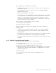


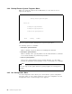
Table Of Contents
- IBM PC Server and Novell NetWare Integration Guide
- Abstract
- Contents
- Figures
- Tables
- Special Notices
- Preface
- Chapter 1. IBM PC Server Technologies
- Processors
- Clock Rate
- External Interfaces
- Processor Types
- Multiprocessing
- Memory
- Caches
- Memory Interleaving
- Dual Path Buses
- SynchroStream Technology
- Memory Error Detection and Correction
- Standard (Parity) Memory
- Error Correcting Code (ECC)
- Error Correcting Code- Parity Memory (ECC- P)
- ECC on SIMMs (EOS) Memory
- Performance Impact
- Memory Options and Speed
- Bus Architectures
- ISA Bus
- EISA Bus
- Micro Channel Bus
- PCI Bus
- Disk Subsystem
- Hard Disk Interfaces
- SCSI Technology
- SCSI Adapters
- Hard Disk Drives
- RAID Technology
- RAID Classifications
- Recommendations
- LAN Subsystem
- Shared RAM Adapters
- Bus Master Adapters
- PeerMaster Technology
- Security Features
- Tamper- Evident Cover
- Secure I/ O Cables
- Passwords
- Secure Removable Media
- Selectable Drive Startup
- Unattended Start Mode
- Systems Management
- DMI
- SNMP
- NetFinity
- SystemView
- Fault Tolerance
- NetWare SFT III
- Uninterruptible Power Supply (UPS)
- APC PowerChute
- Chapter 2. IBM PC Server Family Overview
- Chapter 3. Hardware Configuration
- The Setup Program
- Main Menu
- Advanced Menu
- Security
- EISA Configuration Utility
- SCSI Select Utility Program
- System Programs
- Starting From the System Partition
- Starting From the Reference Diskette
- Main Menu Options
- Backup/ Restore System Programs Menu
- Set Configuration Menu
- Set Features Menu
- Test the Computer
- More Utilities Menu
- Advanced Diagnostic Program
- RAID Controller Utility
- Drive Information
- Formatting the Disks
- Defining a Hot- Spare Disk
- Creating a Disk Array
- Defining Logical Drives
- Setting the Write Policy
- Initializing the Array
- Backup/ Restoring the Configuration
- Chapter 4. Novell NetWare Installation
- ServerGuide Overview
- Starting ServerGuide
- Installing NetWare 4.1 with ServerGuide
- Installing NetWare 3.12 with Diskettes
- Hardware Requirements
- Software Requirements
- Information Requested at Time of Installation
- Installation Files
- Installation Procedure
- Installing NetWare 4.1 with the Original CD- ROM
- Hardware Requirements
- Software Requirements
- Installation Procedure
- NetFinity Services for NetWare
- System Requirements
- Installing NetFinity Services for NetWare
- The RAID Administration for NetWare Utility
- Installing the Utility
- Hard Disk Failure Simulation
- Simulating with a Hot Spare Drive
- Simulating without a Hot Spare Drive
- Chapter 5. Performance Tuning
- Appendix A. EISA Configuration File
- Appendix B. Hardware Compatibility, Device Driver, and Software Patch Information
- Appendix C. Configuring DOS CD-ROM Support
- List of Abbreviations
- Index
- Special Characters C
- Numerics
- A
- B
- D
- E
- F
- H
- M
- I
- N
- K
- L
- O
- P
- S
- Q
- R
- T
- U
- V
- W
- Z
- ITSO Technical Bulletin Evaluation RED000

The fields on this panel are described as follows:
SCSI Parity Checking:
Select this option to enable or disable SCSI Parity
checking on the host adapter. If enabled, the host adapter will check parity when
reading from the SCSI bus to verify the correct transmission of data from your
SCSI devices. SCSI Parity checking should be disabled if any attached SCSI
device does not support SCSI parity. Most currently available SCSI devices do
support SCSI parity.
Host Adapter SCSI termination:
All SCSI interfaces use daisy-chain cabling.
The cable starts at the adapter and goes to the first device, and then out of that
device to the next device and so on until it reaches the last device in the chain.
The last device has an incoming cable and a
terminator
. The terminators are
used to absorb potential signal reflections on the SCSI bus which would cause
interference. The last device on the bus must always be terminated.
The SCSI-2 Fast/Wide PCI adapter that came with the PCI/EISA server has three
connectors which can be the starting points for a daisy-chained cable: one 8-bit,
50-pin (SCSI-I) internal connector, one 16-bit, 68-pin (SCSI-II Wide) internal cable
connector, plus another 16-bit, 68-pin external connector. The adapter has
built-in terminators on these connectors.
The setting for the Host Adapter SCSI termination needs to be configured
depending on which connectors are used. This option is comprised of two
entries, a low and a high. You can think of them as software jumpers. Each
entry, low and high, can take on either an on or off value, thereby giving four
possible different combinations of the two entries. The chart below shows the
proper values of these entries depending upon what connectors have been used.
Note
Only two of the three connectors can be used, either the two internal or one
internal and one external.
After configuring the host adapter, you need to configure the SCSI devices. To
do this:
•
Use the arrow keys to select SCSI Device Configuration
•
Press Enter
A screen like the one in Figure 36 on page 80 will appear:
Table 16. Host Adapter SCSI Termination Parameter
16-bit (68pin)
internal connector
8-bit (50pin)
internal connector
16-bit (68pin)
external
connector
Low
value
High
value
Yes On On
Yes On On
Yes On On
Yes Yes Off Off
Yes Yes Off On
Yes Yes Off On
Chapter 3. Hardware Configuration 79