
Technical information


Appendix A. Connector Pin Assignments
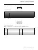
USB Connector
4
3
2
1
Figure 8. USB Connector
Infrared Port Connector
1
5
69
Figure 9. Infrared Port Connector
Note: The external interface for the infrared port is a female, 9-pin D-shell connector.
Table 46. 4-Pin Assignments for the USB Connector
Pin Signal Name
1 VCC
2 -Data
3 +Data
4 Ground
Table 47. 9-Pin Assignments for the Infrared Connector
Pin Signal Name Pin Signal Name
1 IR transmitted data (output) 2 Ground
3 Reserved 4 IR module select 2
5 IR module select 1 6 IR received data (input)
7 Voltage (+5 V dc) 8 IR module select 0
9 No connect
Appendix A. Connector Pin Assignments 37