
Technical information


Appendix A. Connector Pin Assignments
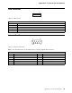
Diskette Drive Connector
1
2
34
33
Figure 4. Diskette Drive Connector
Note: The connector for the diskette drive is a 34-pin, berg strip.
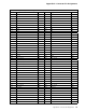
Table 41. 34-Pin Assignments for the Diskette Drive Connector
Pin Signal Name I/O Pin Signal Name I/O
1 Reserved I 2 High density select O
3 Not connected NA 4 Not connected NA
5 Ground NA 6 Data rate 0 NA
7 Ground NA 8 Index# I
9 Reserved NA 10 Motor enable 0 O
11 Ground NA 12 Drive select 1 O
13 Ground NA 14 Drive select 0 O
15 Ground NA 16 Motor enable 1 O
17 MSEN1 I 18 Direction in# O
19 Ground NA 20 Step# O
21 Ground NA 22 Write data# O
23 Ground NA 24 Write enable# O
25 Ground NA 26 Track0# I
27 MSEN0 I 28 Write protect# I
29 Ground NA 30 Read data# I
31 Ground NA 32 Head 1 select# O
33 Data rate 1 NA 34 Diskette change# I
34 Technical Information Manual