
Technical information


Chapter 4. Power Supply
Power Connectors
Note: The total power used by the any of following connectors must not exceed the amount shown in
“Component Outputs” on page 21.
The power supply provides 4-pin connectors for attaching internal devices. The following table lists the pin
assignments for these connectors.
Connectors with 6 pins are used to connect the power supply to the system board and riser card. The
following table lists the pin assignments for these connectors.
Connectors with 3 pins are provided to connect the power supply with the system board and a LAN
feature. The following table lists the pin assignments for these connectors.
Table 28. Pin Assignments for 4-Pin Power Connectors
Connector Location Pin 1 Pin 2 Pin 3 Pin 4
P3 3.5-inch diskette drive +5 V Ground Ground +12 V
P4 – +12 V Ground Ground +5 V
P5 DASD +12 V Ground Ground +5 V
P6 DASD +12 V Ground Ground +5 V
P7 DASD +12 V Ground Ground +5 V
P8 DASD +12 V Ground Ground +5 V
Table 29. Pin Assignments for 6-Pin Power Connectors
Connector Location Pin 1 Pin 2 Pin 3 Pin 4 Pin 5 Pin 6
P1 System board Power
Good
+5 V +12 V −12 V Ground Ground
P2 System board Ground Ground −5 V +5 V +5 V +5 V
P10 Riser 3 V +3.3 V +3.3 V +3.3 V Ground Ground Ground
P11 System board
3 V
+3.3 V +3.3 V +3.3 V Ground Ground Ground
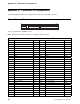
Table 30. Pin Assignments for 3-Pin Power Connectors
Connector Location Pin 1 Pin 2 Pin 3
P9
6
System board +5 V Control Ground
P12 LAN +5 V Control Ground
6
AUX 5
Chapter 4. Power Supply
23