
Technical information


Chapter 2. System Board Features
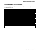
Connections and the CMOS-Clear Jumper
Connections and jumpers on the system board allow custom configurations. The following tables list the
pin descriptions for specific connections and the CMOS-clear jumper. To locate these components, see
“System Board” on page 14.
Table 9. J3 - System Power Connection
Pin Description
1 Auxiliary (+5 V dc)
2 Power switch input
Table 10. J11, J13 - Wake on Modem Ring Connections
Pin Description
1 Ground
2 Wake on Modem/Ring
Table 11. J15 - Wake on LAN Connection
Pin Description
1 Ground
2 External Wake on LAN/Ring
Table 12. J8 - CMOS-Clear Jumper
Pin Description
1 and 2 Normal
2 and 3 Clear CMOS
Chapter 2. System Board Features 15