
Technical information


Chapter 2. System Board Features
Physical Layout
The system board might look slightly different from the one shown.
Note: A diagram of the system board, including switch and jumper settings, is attached to the underside
of the computer top cover.
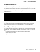
System Board
.1/ Parallel port connector
.2/ Universal serial bus port connector
.3/ Riser connector
.4/ Serial port connector
.5/ Mouse port connector
.6/ Keyboard port connector
.7/ J15 - Wake on LAN connector
.8/ Infrared port connector
.9/ 5 V auxiliary connector
.1ð/ J3 - Power switch connector
.11/ J8 - CMOS-clear jumper
.12/ Diskette connector
.13/ Microprocessor/diskette write-protection switches
.14/ SCSI LED connector
.15/ J13 - Wake on modem connector
.16/ J11 - Wake on modem connector
.17/ Primary EIDE connector
.18/ Secondary EIDE connector
.19/ Battery
.2ð/ Power connector
.21/ Power connector
.22/ Second microprocessor socket
.23/ Fan connector for second microprocessor
.24/ VRM connector
.25/ Primary microprocessor
.26/ J26 - Power LED connector
.27/ J30 - Front panel fan connector
.28/ System memory (DIMM) connectors
Figure 1. System Board
14 Technical Information Manual