
Specifications
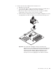
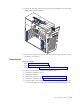
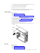

6. To remove the power-switch and LED panel, press in on the tab on the left
side of the panel; then, squeeze the top and bottom of the right side of the
panel, and carefully pull the panel away from the computer.
7. Note where the power-switch and LED panel cable is connected to the system
board; then, carefully disconnect the cable from the system board.
Notes:
a. You might need to remove the diskette and IDE cables to access the
power switch and LED panel cable connector.
b. Some cables might have two connectors for you to disconnect.
c. See the system service label for system board connector locations.
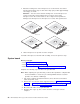
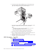
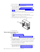
8. Disconnect the cable of the power button from the system board.
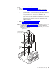
9. Place a screwdriver against the bottom release latch of the power button; then,
gently press upward, and slide the latch through the aperture.
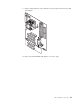
10. Gently pinch together the upper release latches; then, slide the latches through
the aperture, and remove the power button.
IEEE 1394 adapter — Type 6230
Before you begin:
v Read “Safety information” on page 129.
v Read “Installation guidelines” on page 31.
v Review the information in “System reliability considerations” on page 31.
1.
Turn off the computer, and remove external cables. See “Turning off the
computer” on page 10.
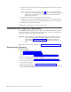
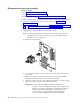
2. Remove the cover and support bracket (see “Removing the side cover” on page
52 and “Removing and installing the support bracket” on page 53).
3. Disconnect any cables that impede access to the mini-PCI IEEE 1394 adapter.
86 IBM IntelliStation M Pro Types 6220 and 6230: Hardware Maintenance Manual