
Specifications
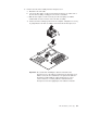
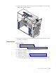
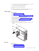

7. Remove the 12 screws that secure the system board to the chassis, and put
them in a safe place.
Note: Four of the screws described in step 7 secure the heat-sink retention
module to the heat-sink retention clip, with the system board in between
them. It is easier to remove these screws while the system board is
positioned in the chassis.
8. Remove the heat-sink retention module, and set it aside.
9. Gently slide the system board slightly toward the front of the computer until it
disengages from the chassis; then, lift the board up and out of the computer.
10. Remove the heat-sink retention clip.
To
install the system board, reverse the previous steps.
IntelliStation M Pro Type 6230 (tower model)
The following information describes procedures for removing and installing certain
components inside the system. Only a qualified service technician is authorized to
access the components described in this section.
Important: The field replaceable unit (FRU) procedures are intended for trained
servicers who are familiar with IBM IntelliStation products. See the
parts listing in “Type 6230” on page 122 to determine whether the
component being replaced is a customer replaceable unit (CRU) or a
FRU.
Note:
Before servicing this computer, read “Installation guidelines” on page 31.
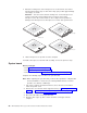
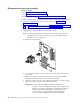
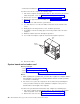
Removing the front bezel
Before you begin:
v Read “Safety information” on page 129.
v Read “Installation guidelines” on page 31.
v Review the information in “System reliability considerations” on page 31.
Complete
the following steps to remove the bezel:
1. Review the information in “System reliability considerations” on page 31.
2. Turn off the server and peripheral devices, and disconnect all power cords and
then all external cables.
3. Remove the side cover (see “Removing the side cover” on page 52).
4. Press the bezel-release latch at the top of the computer to disconnect the top of
the bezel from the computer.
84 IBM IntelliStation M Pro Types 6220 and 6230: Hardware Maintenance Manual