
Specifications
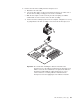
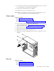

7. Rotate the locking lever on the microprocessor socket from its closed and
locked position until it stops or clicks in the fully open position (approximately
135° angle), as shown.
Attention: You must ensure that the locking lever on the microprocessor
socket is in the fully open position before you remove or insert the
microprocessor in the socket. Failure to do so might result in permanent
damage to the microprocessor, microprocessor socket, and system board.
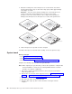
Lever closed
Lever open
Lever closed
Lever open
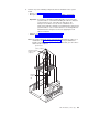
8. Lift the microprocessor up and out of the computer.
To
install a microprocessor and fan-sink assembly, reverse the previous steps.
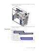
System board
Before you begin:
v Read “Safety information” on page 129.
v Read “Installation guidelines” on page 31.
v Review the information in “System reliability considerations” on page 31.
Complete
the following steps to remove the system board.
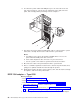
Note: When replacing the system board, you must either update the computer with
the latest firmware or restore the pre-existing firmware that the customer
provides on a diskette or CD image.
1. Turn off the computer and attached devices; then, disconnect all external
cables and power cords.
2. Remove the cover and the frame-support bracket (see“Removing the cover” on
page 34 and “Removing and installing the support bracket” on page 35).
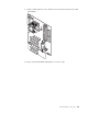
3. Remove the air baffle (see “Baffle” on page 75).
4. Disconnect all cables on the system board.
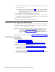
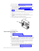
5. Pivot the drive cages up; then, remove the drives and cages from the
computer.
82 IBM IntelliStation M Pro Types 6220 and 6230: Hardware Maintenance Manual