
Specifications

marketing representative. To receive an indication of SCSI hard-disk drive activity,
you must also connect the SCSI adapter to the SCSI LED connector on the system
board. See “System-board internal connectors” on page 51 for the location of the
SCSI connectors.
Setting SCSI IDs
Each SCSI device connected to a SCSI controller must have a unique SCSI ID.
This ID enables the SCSI controller to identify the device and ensure that different
devices on the same SCSI channel do not attempt to transfer data simultaneously.
SCSI devices that are connected to different SCSI channels can have duplicate
SCSI IDs. See the information that is provided with the device for instructions about
setting its SCSI ID.
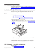
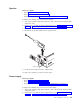
Universal serial bus (USB) connectors
There are six Universal Serial Bus (USB) 2.0 connectors, two on the front and four
on the rear of the computer. Use the USB connectors to connect optional telephony
and multimedia devices. USB 2.0 technology transfers data at up to 480 Mb per
second (Mbps) with a maximum of 127 external devices and a maximum signal
distance of 5 meters (16 ft) per segment (if the device that is attached to the
computer is a USB 2.0 device). If multiple USB devices are attached to the
computer, the USB hub must be USB 2.0, otherwise, all USB 2.0 devices will
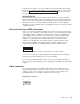
transfer data at 12 Mbps. Using Plug and Play technology, USB devices are
configured automatically. The following illustration shows a USB connector.
14
Use a 4-pin USB cable to connect external devices to USB connectors.
If you connect a PS/2 (non-USB) keyboard to the keyboard connector, USB ports
and devices are disabled during power-on self-test (POST).
If you connect a USB keyboard that has a mouse port, the keyboard emulates a
mouse, and you cannot disable the mouse settings in the Configuration/Setup Utility
program.
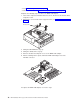
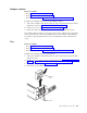
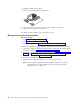
Video connector
The Accelerated Graphics Port (AGP) adapter, which is in the AGP slot on the
system board, provides the video connector. This connector is on the rear of the
computer. Use the video connector to connect a monitor or other display. The
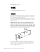
following illustrations are examples of different video connectors.
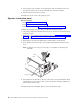
Analog video connector
1
5
1115
Installing options 73