
Specifications
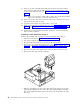
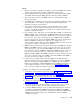
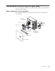

13. Connect one end of the IDE signal cable into the back of the drive and the
other end of the cable into the IDE connector on the system board. For the
location of the IDE connectors, see “System-board internal connectors” on
page 33
Note: Make sure to route the signal cable so that it does not block the airflow
to the rear of the drives or over the microprocessor.
14. Connect the power cable to the back of the drive. The connectors are keyed
and can be inserted only one way.
15. If you have other options to install or remove, do so now.
16. Replace the frame-support bracket and cover. See “Replacing the cover” on
page 47 and “Removing and installing the support bracket” on page 35 for
details.
17. Reconnect the external cables and power cords; then, turn on the attached
devices and the computer.
Installing a hard disk drive in bay 3
Complete the following steps to replace or install a hard disk drive in bay 3:
1. Follow the instructions in “Preinstallation steps” on page 38.
2. Turn off the computer and attached devices.
3. Disconnect all power cords; then, disconnect all external cables.
4. Remove the cover and frame-support bracket. See “Removing the cover” on
page 34 and “Removing and installing the support bracket” on page 35 for
details.
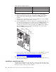
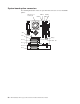
5. Disconnect the power and signal cables from both drives in the drive cage.
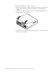
6. Remove the drive cage from the computer.
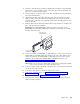
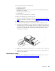
7. Slide the existing drive out of the drive bay. Remove the drive from the drive
tray by gently pulling both sides of the drive tray outward until the mounting
pins are disengaged from the holes on the drive; then, lift the drive out of the
drive tray.
42 IBM IntelliStation M Pro Types 6220 and 6230: Hardware Maintenance Manual