
Operating instructions


Marquette Hellige GmbH CardioSys / MicroLab V4.X Page 87
Servicing Instructions 227 436 37 Rev. B V1.3
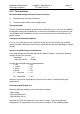
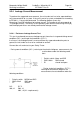
Electrical Diagram for Enclosure Leakage Current Test
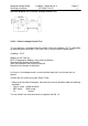
9.2.4.2 Patient Leakage Current Test
This test performs a leakage current test under single fault conditions (S.F.C.) depending
on domestic power outlet with 115 or 230 V AC as source into the floating inputs.
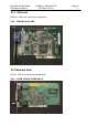
CardioSys : ECG
Modules in the Tram-rac:
BP/CO/Temperature Modules: refer to Service Manual
Document Part Number 403798-005
Solar SpO2 Module: refer to Service Manual
Document Part Number 414993-033
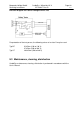
In all cases, the leakage current is measured from input jack, of unit under test, to
ground.
Connect the unit under test to your Safety Tester.
-. Referring to the electrical diagram, measurements have to be done under the following
conditions:
* Polarity switch NORM and RVS
* GND switch GND closed
* S1 closed
Test has failed if the measured values are greater than 50 µA