
Operating instructions


Marquette Hellige GmbH CardioSys / MicroLab V4.X Page 86
Servicing Instructions 227 436 37 Rev. B V1.3
9.2.4 Leakage Current Measurement
To perform the suggested measurements, the unit under test has to be separated from
any interconnection to a system. If the unit is part of a system, extended tests according
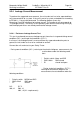
to IEC 601-1-1 have to be performed. The following diagram shows the
Measuring Circuit [M] reference for leakage current. The reading in mV corresponds to
µA (leakage current). The Safety Testers generally work with this Measuring Circuit [M]
and the displayed values are already converted to leakage current.
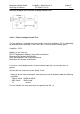
9.2.4.1 Enclosure Leakage Current Test
This test is performed to measure leakage current from chassis to ground during normal
conditions (N.C.) and single fault conditions (S.F.C.).
In all cases, the leakage current is measured from any exposed conductive parts to
ground, the unit under test has to be switched on and off.
Connect the unit under test to your Safety Tester.
- During normal conditions (N.C.), referring to the electrical diagram, measurements ha-
ve to be done under the following condi-
tions:
* Polarity switch Norm and RVS
* GND switch GND closed
* S1 closed and open
- During single fault conditions (S.F.C.),
referring to the electrical diagram, the
measurements have to be done under the
following conditions:
* Polarity switch NORM and RVS
* GND switch GND open
* S1 closed
N.C. S.F.C
100 µA 500 µA
300 µA (U.L. requirements)