
Operating instructions


Marquette Hellige GmbH CardioSys / MicroLab V4.X Page 85
Servicing Instructions 227 436 37 Rev. B V1.3
Identification of disconnected electrodes
Reset the simulator to ECG signal at a heart rate of 60 bpm. Remove one electrode after
the other from the ECG transmitter.
Call up the resting ECG recording screen. Check to ensure that each disconnected
electrode is displayed correctly and that an acoustic alarm signal sounds (check
beforehand that the acoustic electrode alarm signal is enabled.)
9.2 Safety Analysis Test
9.2.1 General introduction
The suggested Safety Analysis Tests refer to the international standard IEC 601-1.
The tests are generally performed with Safety Testers, on most of them, the measuring
circuits according IEC 601 are already
implemented.
The following is a general description of the tests to be performed. For the handling of
your Safety Tester follow the user manual.
The tests may be performed under normal ambient conditions of temperature, humidity
and pressure and with line voltage.
The leakage currents correspond to 110 % of rated voltage for the tested unit. Most
Safety Testers take this into account,
otherwise the measured values have to be calculated.
9.2.2 Recommended Test Equipment
- Safety Tester for measurements according to IEC 601.
- Testing connector according to the following description.
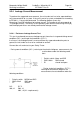
9.2.3 Pretective Earth Resistance Test
The power cord is to be included in the protective earth resistance test.
This test determines whether the device has a power ground fault.
- The protective earth resistance from power connector to any protective earth
connected exposed conductive part is measured.
- Specs. of test circuit: AC current source 50 Hz/60 Hz of at least 10 A up to 25 A
with limited output voltage of 6 V.
- If resistance is greater than 100 mOhm , the unit fails this test.