
Operating instructions


Marquette Hellige GmbH CardioSys / MicroLab V4.X Page 40
Servicing Instructions 227 436 37 Rev. B V1.3
Installing the Additional Protective Earth Conductor in
CardioSys / MicroLab Systems
When operating the printer in conjunction with CardioSys / MicroLab in the patient
environment (1.5 m), an authorized service technician is required to install an additional
protective earth conductor as described below.
Parts set Printer EPL5700: Marquette Hellige Part No. 384 018 83
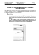
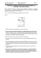
Figure 1
1. Switch off printer and disconnect power cord from wall outlet.
2. Unscrew the potential equalization cable PE at CardioSys/MicroLab (see Figure 1) and
pull out as much of the cable as needed to connect the cable at the rear of the printer.
(When the CardioSys system is an older model (without potential equalization cable for
the printer) a separate potential equalization cable should be installed in parallel with the
printer power cord and connected to ground (GND).
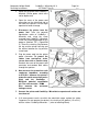
3. Remove the two screws on the rear of the printer (see Figure 2).
4. Using these screws and the tooth lock washers, attach the supplied ground strip (see
Figure 2).
5. Now take the potential equalization cable from CardioSys/MicroLab and screw it to the
ground strip provided for this purpose (see Figure 2). Attach the mounting accessories in
the following order: tooth lock washer, cable lug, tooth lock washer, washer and M4 nut
(Figure 2).
6. To protect the potential equalization cable from mechanical strain, secure it with the
supplied cable tie.
7. Now measure the protective earth conductor impedance according to IEC 601-1
between the printer's protective earth connection (mains plug) and the ground
strip. Make a second measurement of the protective earth conductor impedance
between the protective earth connection (mains connector) of