
Operating instructions


Marquette Hellige GmbH CORINA Page 32
Version 2.0 227 437 01 D
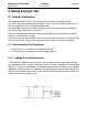
5.1.2.3 Enclosure Leakage Current Test (System)
IMPORTANT
Do not operate devices (PC / VGA Monitor / Printer / ...) in the vicinty of the patient
(1,5m / 5ft.) if there are not in the condition with IEC 601-1!
All units there are connected to the CardioSoft system (PC / VGA Monitor / Printer / ...) has
to be tested as follow.
Connect all power cords from the units sepatartly for test to your Safety Tester.
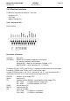
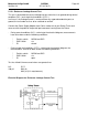
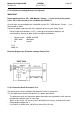
- During single fault conditions (S.F.C.), referring to the electrical diagram, the
measurements have to be done under the following conditions:
* Polarity switch NORM and RVS
* GND switch GND open
* S1 closed
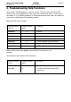
S.F.C
3500 µA
Electrical Diagram for Enclosure Leakage Current Test
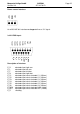
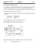
5.1.2.4 Protective Earth Resistance Test
The power cord is to be included in the protective earth resistance test.
This test determines whether the device has a power ground fault.
- The protective earth resistance from power connector to any protective earth connect-
ed exposed conductive part is measured.
- Specs. of test circuit: AC current source 50 Hz/60 Hz of at least 10 A up to 25 A with
limited output voltage of 6 V.
- If resistance is greater than 100 mOhm, the unit fails this test.