
Operating instructions

Marquette Hellige GmbH CORINA Page 30
Version 2.0 227 437 01 D
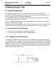
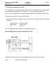
5.1.2.1 Enclosure Leakage Current Test
This test is performed to measure leakage current from chassis to ground during normal
conditions (N.C.) and single fault conditions (S.F.C.).
In all cases, the leakage current is measured from any exposed conductive parts to
ground, the unit under test has to be switched on and off.
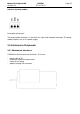
Connect the Power Supply Adapter from Corina under test to your Safety Tester and
measure with the probe to the parallel port connector housing from the Corina.
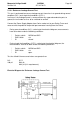
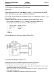
- During normal conditions (N.C.), referring to the electrical diagram, measurements
have to be done under the following conditions:
* Polarity switch NORM and RVS
* GND switch n/a
* S1 closed
- During single fault conditions (S.F.C.), referring to the electrical diagram, the
measurements have to be done under the following conditions:
* Polarity switch NORM and RVS
* GND switch n/a
* S1 open
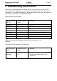
Test has failed if the measured values are greater than:
N.C. S.F.C
100 µA 500 µA
300 µA (U.L. requirements)
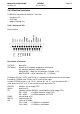
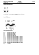
Electrical Diagram for Enclosure Leakage Current Test