
Operating instructions


Marquette Hellige GmbH CORINA Page 21
Version 2.0 227 437 01 D
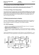
voltage from the 12 V received from the plug-in power supply. The DC/DC transducer can
be switched on and off by the PC via the control cable. There is a connector on the PC to
connect the 12 V. The pump module can then be connected to this connector.
Data communication between PC and CORINA is via a FIFO. This enables the PC to pick
up ECG data at any time. The FIFO has a memory depth of 8 K / 32K X 9 bits, 7/3 bits
being used (of these, 6/3 bits for ECG data and 1 bit for synchronization).
All output leads are led through a driver chip.
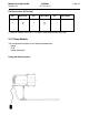
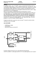
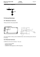
3.2.4 Optional Analog Out Electronics
The PCB CORINA TRIGGER provides the user with a floating analog ECG output signal
for connection to ultrasound units. Pacing pulses are blanked out.
Funtionality:
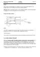
Using QSPI (serial data transfer) the ECG data are transmitted via a medically floating
segment to a D/A transducer (10 bits) located on the PCB CORINA TRIGGER. The analog
output signal is subsequently standardized, amplified and made available to the user. The
signal is short-circuit-proof, unfiltered and does not have ADS bedside processing.
Caution: To enable QRS complex triggering when using PACE, the pacing pulses are
removed from the ECG signal.
non-
floating
floating
Data via
QSPI
POWER
+12V
+12V
-12V
5V
Reg.
DC/DC
Converter
Opto-
Couplers
DA-
Converter
Analog
Amplifiers
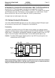
When connecting up an ultrasound unit it is important to ensure that the instrument
connected has an input LPF of < 400 Hz. If this is not the case, an external (passive)
low pass should connected to the input of the peripheral.