
Operating instructions


Marquette Hellige GmbH CORINA Page 20
Version 2.0 227 437 01 D
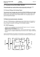
Memory:
A 128 kByte FLASH ( 128 K x 8 PEROM ), which can be programmed directly with the
5-V operating voltage supply, is used as a program memory store. This permits the subse-
quent loading of software updates using the PC. The data memory comprises the ON-The
interrupt requests IEKG_and IPCPW_ are both stored by using FLIPFLOPS, since the
interrupt inputs IRQ1 to IRQ6 are only level gated. In contrast to the others, IRQ7 is edge
gated and can thus be actuated directly.
Resets are generated by a MICROPROCESSOR SUPERVISORY CIRCUIT.
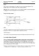
A floating section is used to connect the functional unit ECG Processor to the QSPI inter-
face of the 68332. This is a full duplex interface with data input MISO ( Master-In Slave-
Out ), data output MOSI ( Master-Out Slave-In ) and serial clock SCK. A maximum of 4
devices can be connected to this interface. To achieve this, the PCB is equipped with a
connector onto which this bus can be switched in. Using this connector thus allows the
connection of a maximum of 3 further peripherals (e.g., experimental input). One of the
peripherals is the PCB CORINA TRIGGER (optional).
A signal transmitter gives an acoustic status message. This signal transmitter enables
signalling of errors, for example.
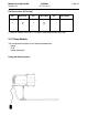
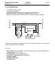
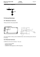
3.2.3 PC PORT:
- CORINA power supply
- ESD protection
- data communication to and from PC
12V
FIFO
ESD
Control-Bus
Data-Bus
ESD
D
r
i
v
e
r
5V
Supply
5V
t
o
P
C
t
o
C
O
N
T
R
O
L
L
E
R
5V (direct)
I
N
P
U
T
All cables leading to and from the PC are provided with ESD protection.
A DC/DC transducer is used to generate the 5 V. This transducer generates the 5-V power