
Operating instructions


Marquette Hellige GmbH CORINA Page 18
Version 2.0 227 437 01 D
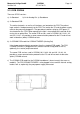
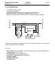
3.1.7 Insulation Foil for PCB CORINA TRIGGER
The insulation foil serves to effect floating isolation of the analog section of the PCB
CORINA TRIGGER with reference to the casing and (optionally) to the pump.
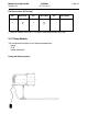
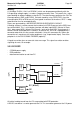
3.1.8 Internal Wiring of the Analog Output
The connection from the analog output of the PCB CORINA TRIGGER to the 3-pin output
socket on the casing is effected using a lead covered by a heat-shrinkable tube. For EMV
purposes there are two wide-band interference suppression coils inside this tube. Using
this tube effects high-voltage-resistant isolation between the analog output signal and
ground and patient floating part.
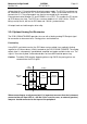
3.2 Electrical and electronic structure
The entire CORINA electronics is divided up into three functional units and located on a
PCB. These are ECG CONDITIONING, CONTROLLER and PC PORT. (In addition, op-
tionally, Analog Out electronics on the plug-in PCB CORINA TRIGGER).
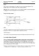
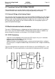
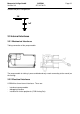
3.2.1 ECG Processing
- acquisition and analog-digital conversion of the ECG signals via up to 11 electrodes
- preprocessing and intermediate storage of the data
- data transfer via a serial interface
- additional functions are: pace identification, checking and testing functions, configura-
tion of the inputs, N negative-feedback loop, measurement of d.c. voltage and blocking
function
Transfer of data between the functional unit ECG Processor and CONTROLLER is via a
QSPI interface. The exact specifications are described in the document [ASIC Interface].
P
a
t
i
e
n
t
-
C
a
b
l
e
S
i
g
n
a
l
I
m
p
u
t
P
r
o
t
e
c
t
i
o
n
C
o
n
t
r
o
l
l
e
r
O
p
t
o
c
o
u
p
l
e
r
D
C
-
D
C
T
r
a
n
s
f
o
r
m
e
r
5V
Clock
ASIC1
ASIC1
ASIC2
ASIC3
P
r
e
a
m
p
l
i
f
i
e
r
F
l
o
a
t
i
n
g
-
p
a
t
h