
Operating instructions


Marquette Hellige GmbH CORINA Page 17
Version 2.0 227 437 01 D
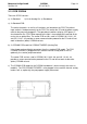
Pump:
When using the PCB Analog Out the power line to the suction pump (optional) is not
plugged into the PCB CORINA, but the PCB CORINA TRIGGER.
Important: When used together with the PCB CORINA TRIGGER, the braided pumppow-
er supply wires must be covered by a heat-shrinkable tube!
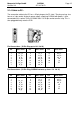
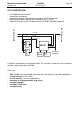
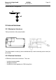
Pump (new tubing system)
PCB:
The PCB is screwed onto the pump casing. The electronics for pressure regulation is
located on the PCB. The 12-V power cable is soldered to the PCB.
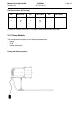
Tubing connection:
The air tubing is preassembled and only needs connecting to the nozzle (on the casing).
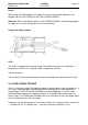
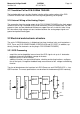
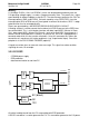
3.1.6 PCB CORINA TRIGGER
There is a floating, analog ECG output based on an optional plug-in card. It provides a 1V/
1mV signal (unedited signal, without filter and ADS, pacing pulse is blanked out)at the
analog output. The PCB CORINA TRIGGER only needs plugging in. It remains firmly
attached without requiring any additional fixation. The standard signal to be output is a
lead II signal. For CORINA and CardioSoft Version 3.0 and later versions the output signal
can be configured in the stress test mode.
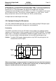
Peripherals can be connected via a 3-pin output socket. Pin assignment of this socket: Pin
1 = Analog Out, Pin 2 = ground, Pin 3 = reserved (also refer to Section 3.4.2.3)