
Operating instructions


Marquette Hellige GmbH CORINA Page 14
Version 2.0 227 437 01 D
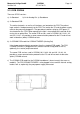
3.1.3 PCB CORINA
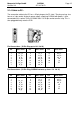
There are 5 PCB versions:
a) 2x Standard b) 2x for Analog Out c) Standalone
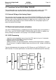
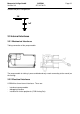
a) 2x Standard PCB:
The entire electronics as well as all interfaces are located on the PCB. The patient
input socket is fixed permanently to the PCB. The lead to the PC and the power supply
cable to the pump are plugged in. The operational readiness display (LED green) is
also located on the PCB. When operative the light is transmitted to the outside of the
casing via an optical fiber. The newer PCB version, used in CORINA 101 118 31...32
and 101 118 41...42 provides a newer communication protocoll to the PC and will not
work inside other (older) CORINA variants.
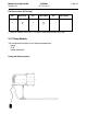
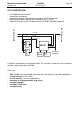
b) 2x CORINA PCB model for CORINA TRIGGER (Analog Out)
It has longer male multipoint connectors than the standard PCB model. The PCB
CORINA TRIGGER is plugged into this and the internal analog lead as well as,
optionally, the suction pump connected.
The newer PCB version, used in CORINA 101 118 33...36 and 101 118 43...44
provides a newer communication protocoll to the PC and will not work inside other
(older) CORINA variants.
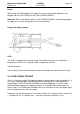
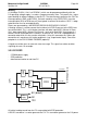
c) The CORINA PCB model for the CORINA standalone is almost exactly the same as
model b). The PCB CORINA TRIGGER is also plugged in here and the internal analog
lead as well as, optionally, the pump power supply connected.