
Operating instructions


Marquette Hellige GmbH CORINA Page 3
Version 2.0 227 437 01 D
Contents
1. Context......... .................................................................................................................. 5
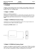
1.1 Model 1 CORINA ............................................................................................... 5
1.2 Model 2 CORINA with Suction Pump................................................................. 5
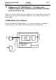
1.3 Model 3 CORINA with Analog Output ................................................................ 5
1.4 Model 4 CORINA with Suction Pump and Analog Output .................................. 6
1.5 Model 5 CORINA Standalone ............................................................................ 6
1.6 Model 6 CORINA Standalone with Suction Pump.............................................. 6
1.7 Replacement of CORINA Model 1...4 through newer CORINA Variants with
enhanced communication interface to PC (101 118 31...44) ............................. 7
2. Introduction ................................................................................................................... 9
2.1. Repair Procedure ................................................................................................. 9
3. Hardware Structure ..................................................................................................... 11
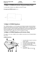
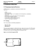
3.1 Physicomechanical Structure .............................................................................. 11
3.1.1 Casing: .................................................................................................... 11
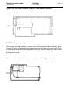
3.1.2 Floating screening:.................................................................................. 12
3.1.3 PCB CORINA.......................................................................................... 14
3.1.4 Cable to PC............................................................................................. 15
3.1.5 Pump Module.......................................................................................... 16
3.1.6 PCB CORINA TRIGGER ........................................................................ 17
3.1.7 Insulation Foil for PCB CORINA TRIGGER ............................................ 18
3.1.8 Internal Wiring of the Analog Output ....................................................... 18
3.2 Electrical and electronic structure ....................................................................... 18
3.2.1 ECG Processing ..................................................................................... 18
3.2.2 CONTROLLER: ...................................................................................... 19
3.2.3 PC PORT ................................................................................................ 20
3.2.4 Optional Analog Out Electronics ............................................................. 21
3.3 Internal Interfaces ............................................................................................... 22
3.3.1 Mechanical Interfaces ............................................................................. 22
3.3.2 Electrical Interfaces................................................................................. 22
3.4 Interfaces to Peripherals ..................................................................................... 23
3.4.1 Mechanical Interfaces ............................................................................. 23
3.4.2 Electrical Interfaces.......................................................................................... 24
3.4.2.1 Interface to PC: ............................................................................ 24
3.4.2.2 ECG Input: ................................................................................... 25
3.4.2.3 Analog Out ................................................................................... 26
4. Troubleshooting Help Functions ............................................................................... 27
5. Safety Analysis Test .................................................................................................... 29
5.1 General introduction............................................................................................ 29
5.1.1 Recommended Test Equipment .............................................................. 29
5.1.2 Leakage Current Measurement ............................................................. 29
5.1.2.1 Enclosure Leakage Current Test.................................................. 30
5.1.2.2 Patient Leakage Current Test ...................................................... 31
5.1.2.3 Enclosure Leakage Current Test (System) .................................. 32
5.1.2.4 Protective Earth Resistance Test ................................................. 32
6. Technical Specifications............................................................................................. 33
7. Spare Part List ............................................................................................................. 35
8. Reference Drawings.................................................................................................... 37
9. Appendix: Drawings.................................................................................................... 39