
Operating instructions


4
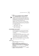
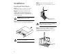
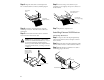
Step 3:
Align the SCSI cable’s colored stripe with
Pin-1 on the SCSI device connector, and then plug it in.
Step 4:
Attach the remaining devices using the
remaining connectors. These devices should not be
terminated.
Step 5:
Terminate the SCSI device that is attached
at the end of the internal SCSI cable.
Caution:
If you are attaching an AHA-2910C
between two terminated SCSI devices, or if you
are using both internal and external SCSI
devices, you must disable host adapter SCSI ter-
mination with SCSISelect, (see Using SCSISelect
on page 7).
Step 6:
Connect a DC power cable from your
computer’s power supply to the power connector on
the SCSI device.
Step 7:
Replace the computer cover.
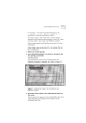
Installing External SCSI Devices
Connecting One Device
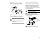
Step 1:
Plug one end of the 50-pin high-density
external SCSI cable into the host adapter’s external
SCSI connector.
Step 2:
Plug the other end of the external SCSI cable
into one of the connectors on the external SCSI device.
Step 3:
Enable the device termination or attach a
terminating plug to the device.
Internal SCSI
Device
Colored Stripe
(typically red or blue)
Pin 1
This device must be
terminated, since it is
connected at the end
of the cable.
You would not terminate
this device.
DC Power Cable
(from the power supply)
Power Input Connector on
the Back of the Drive
Colored Stripe
(typically red or blue)
Pin 1
Terminating Plug
External SCSI Cable