CardioSys/MicroLab Servicing Instructions Version 4.
Caution: During repairs/service interventions, observe the protective measures against damage due to ESD.
Marquette Hellige GmbH Servicing Instructions CardioSys / MicroLab V4.X 227 436 37 Rev. B Page 3 V1.3 Table of Contents 1 General information ................................................................................................................. 7 2 Block diagram........................................................................................................................... 8 3 Functional description ................................................................................
Marquette Hellige GmbH Servicing Instructions CardioSys / MicroLab V4.X 227 436 37 Rev. B Page 4 V1.3 5.2 Installation of the software............................................................................................................24 5.2.1 Installation of CardioSoft ....................................................................................................................25 5.2.2 Installation of CardioSys.................................................................................
Marquette Hellige GmbH Servicing Instructions 8.4.3 8.4.4 8.4.5 8.4.6 8.4.7 8.4.8 8.4.9 8.4.10 8.4.11 8.4.12 8.4.13 8.4.14 CardioSys / MicroLab V4.X 227 436 37 Rev. B Page 5 V1.3 Error messages [3xxx]: Main program...............................................................................................71 Error messages [6xxx]: Resting ECG, Emergency.............................................................................71 Error messages [7xxx]: Ergometry .......................................
Marquette Hellige GmbH Servicing Instructions CardioSys / MicroLab V4.X 227 436 37 Rev. B Page 6 V1.3 REFERENCES Reference Document Title [SA(e)] Servicing Instructions CardioSys V3.0, 227 436 35A REVISION HISTORY Date Version Author Remarks 17.03.99 08.04.99 V 1.0 V 1.1 T.Eberle K.H.Ruh Creation for CardioSys V4.1 Update 30.04.99 V1.2 W.Waltersberger Hardware issues and general rework 25.02.00 V1.3 W.
Marquette Hellige GmbH Servicing Instructions CardioSys / MicroLab V4.X 227 436 37 Rev. B Page 7 V1.
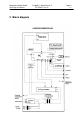
Marquette Hellige GmbH Servicing Instructions 2 Block diagram CardioSys / MicroLab V4.X 227 436 37 Rev. B Page 8 V1.
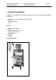
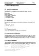
Marquette Hellige GmbH Servicing Instructions CardioSys / MicroLab V4.X 227 436 37 Rev. B Page 9 V1.3 3 Functional description 3.1 Electrical components These comprise all the components which conduct mains voltage. These are: • • • • • mains input power on/off switch mains socket for defibrillator isolating transformer internal power distributer 3.1.1 Mains input The mains input module comprises an IEC plug, the line filter and a fuse holder for two fuses. * 230VT 3.15A (5 x 20) * 115VT 5A (6.
Marquette Hellige GmbH Servicing Instructions CardioSys / MicroLab V4.X 227 436 37 Rev. B Page 10 V1.3 3.1.5 Internal power distributer The system cart has an integrated 6-plug connector inserted downline from the isolating transformer. The following devices are connected to this: 1 2 3...6 PC subassembly Monitor Free for other devices (e.g., respiratory flow sensor plug-in power supply unit) Important: in the US model of CardioSys there is a 15-A fuse in the socket board. 3.2 Computer subassembly 3.
Marquette Hellige GmbH Servicing Instructions CardioSys / MicroLab V4.X 227 436 37 Rev. B Page 11 V1.3 After switching the Power on/off switch to ON, the STANDBY SWITCH near the disk drive must be used to turn the PC-power supply from standby mode to working mode and back. 3.2.3 CPU card CPU Pentium II / 350 cache 512KB memory 64 MB DIMM PC-100 interfaces HDD/FDD EIDE interface, keyboard & mouse interface, 2 serial interfaces, parallel port interface, USB port bus 2 x ISA, 4 x PCI, 1 x AGP 3.2.
Marquette Hellige GmbH Servicing Instructions CardioSys / MicroLab V4.X 227 436 37 Rev. B Page 12 V1.3 3.2.8 Free slots for upgrading The free slots offer the possibility to install further interfaces into the PC. These include the following interfaces: • PCI network card (optional) • PCI SCSI card (optional) • AT-Bus TramNet card (MicroLab only) 3.2.9 Network card An optional PCI Ethernet network card can be installed for network linkup. bus: PCI output: BNC, AUI and TP 3.2.
Marquette Hellige GmbH Servicing Instructions CardioSys / MicroLab V4.X 227 436 37 Rev. B Page 13 V1.3 Formatting Optical Disks You must have system administrator rights before you can do the following steps! There is no possibility to format MO disks in USER Mode. Before saving data to an optical disk, the disk must be formatted. * Insert the disk. * On the Windows screen, select ”Start” —> ”Programs” —> ”Administrative Tools (Common)” —> ”Disk Administrator”.
Marquette Hellige GmbH Servicing Instructions CardioSys / MicroLab V4.X 227 436 37 Rev. B Page 14 V1.3 3.2.12 Streamer DAT An optional DAT streamer can be installed for data backup. memory capacity: 2-4 GByte connection: SCSI-2 interface drive size: 5 ¼” 3.2.13 TRAM-NET card (only in the case of Microlab) PCB TRAM-NET IBM PC INTERFACE 930 117 98 This slot card estabishes communication between the PC and Tram-Rac. 3.
Marquette Hellige GmbH Servicing Instructions CardioSys / MicroLab V4.X 227 436 37 Rev. B Page 15 3.3.2 Function key keyboard The function key keyboard is a special keyboard with keys specifically matched to CardioSys.
Marquette Hellige GmbH Servicing Instructions CardioSys / MicroLab V4.X 227 436 37 Rev. B Page 16 V1.3 3.3.4 Monitor A high-resolution 15" or 17" color monitor is used for text and graphics applications with the following specifications: 15" monitor: * mains input 110V...120V, 1.9A / 220V...240V, 1.1A (autoswitch) 17" monitor: * mains input 110V...120V, 2A / 220V...240V, 1.2A (autoswitch) * high-resolution CRT with 0.
Marquette Hellige GmbH Servicing Instructions * * * * * * * * * * CardioSys / MicroLab V4.X 227 436 37 Rev. B Page 17 V1.3 PS/2 mouse interface keyboard interface monitor interface adaptor connector (COM 1) adaptor connector for ergometer (COM 2) adaptor connector for respiratory flow sensor (COM 3) free serial interface (COM 4) adaptor connector for CORINA (LPT 2) printer port for printer (LPT 1) USB connctor and free slots for further peripherals 3.4.
Marquette Hellige GmbH Servicing Instructions CardioSys / MicroLab V4.X 227 436 37 Rev. B Page 18 V1.3 3.4.3 Mouse/trackball interface The mouse/trackball interface is P S/2 standard! 3.4.4 Respiratory flow sensor interface The respiratory flow interface is one of the four serial interfaces. This interface, hereafter designated COM3, is a standard serial interface in the form of a 9-pin Subm-D adaptor connector (male). 3.4.
Marquette Hellige GmbH Servicing Instructions CardioSys / MicroLab V4.X 227 436 37 Rev. B Page 19 V1.3 3.4.7 CORINA interface The CORINA interface is one of the two parallel interfaces. This interface, hereafter designated LPT2, is a standard printer port in the form of a 25-pin Subm-D adapter connector (female).
Marquette Hellige GmbH Servicing Instructions CardioSys / MicroLab V4.X 227 436 37 Rev. B Page 20 V1.3 3.4.8 Printer port The printer port is one of the two parallel ports. This interface, hereafter designated LPT1, is a standard printer port in the form of a 25-pin Subm-D adapter connector (female). 3.4.9 TRAM-NET interface (Microlab only) 9-pin connector (male) for communication with the Tram-Rac. 3.4.10 Analog output (optional) Analog ECG output specifications: Signal: Gain: Max. amplitude: Max.
Marquette Hellige GmbH Servicing Instructions CardioSys / MicroLab V4.X 227 436 37 Rev. B Page 21 V1.3 4 System/Connector Configuration 4.1 Pentium II PC 220 108 01 PC front view Instead of 70124916 SCSI Controller Adaptec AHA2910 you can also use the newer pcb 2001967-001 SCSI Controller Adaptec AVA 2904.
Marquette Hellige GmbH Servicing Instructions PC top view Connector view CardioSys / MicroLab V4.X 227 436 37 Rev. B Page 22 V1.
Marquette Hellige GmbH Servicing Instructions CardioSys / MicroLab V4.X 227 436 37 Rev. B Page 23 V1.3 5 Installation 5.1 Installation of the hardware components All connectors (including the patient lead) for system components and additional instruments are located under the cover flap. Important: The cover flap may only be opened by the technical staff. The system is supplied ready for operation.
Marquette Hellige GmbH Servicing Instructions CardioSys / MicroLab V4.X 227 436 37 Rev. B Page 24 V1.3 * Patient cable Connect up patient cable to CORINA (patient input). Put ferrite near the connector of this cable. Important: the patient cable may only be connected up to this interface. * Printer (optional) Place printer on the shelf. Connect the printer cable up to the printer and printer port (LPT1).
Marquette Hellige GmbH Servicing Instructions CardioSys / MicroLab V4.X 227 436 37 Rev. B Page 25 V1.3 5.2.1 Installation of CardioSoft For CardioSoft start the Setup Program without parameter. 5.2.2 Installation of CardioSys For CardioSys start the Setup Program with parameter "cardiosys" (for example setup cardiosys). For Software Update start the Setup Program without parameter. 5.2.
Marquette Hellige GmbH Servicing Instructions CardioSys / MicroLab V4.X 227 436 37 Rev. B Page 26 V1.3 Installation Steps: 1. Install CardioSoft V4.1 on the PC 2. Start the CardioSoft Application and view the System Configuration. In the Tab Modem select the Baud Rate and the Modem Type (The Port Setting is not used for the Communication Server). In the Tab MUSE you can configure to send the Rest ECG's to MUSE (The setting "Start Modem connection before transfer" cannot be used).
Marquette Hellige GmbH Servicing Instructions CardioSys / MicroLab V4.X 227 436 37 Rev. B GRA_PrinterFont1 = “...” GRA_PrinterFont2 = “...” GRA_PrinterFont3 = “...” GRA_PrinterFont4 = “...” GRA_PrinterFont5 = “...” // Default =”Times New Roman” // Default =”Arial” // Default =”Courier New” // Default =”Small Fonts” // Default =”Times New Roman” Page 27 V1.
Marquette Hellige GmbH Servicing Instructions CardioSys / MicroLab V4.X 227 436 37 Rev. B CardioSys updates every 5 seconds the shared file with the following string: [recoxxx34xMxxxx0x%xxx60xxxx4x-999x-999x-999xx-19xxxx1xx-12x]4CCR where a space is shown as an 'x'.
Marquette Hellige GmbH Servicing Instructions 10. CardioSys / MicroLab V4.X 227 436 37 Rev. B Page 29 V1.3 The stage names are fixed as the following table shows: Phase Stagenumber Pre-Test Pre-Test ... Exercise ... Recovery ... 1 2 ... 1 ... 1 ...
Marquette Hellige GmbH Servicing Instructions CardioSys / MicroLab V4.X 227 436 37 Rev. B GRA_CharSet=? Page 30 V1.3 // Range of values: 0..4 Default: 0 // Meaning: Determines the character set for the CardioSoft fonts. 0: ANSI_CHARSET 1: DEFAULT_CHARSET 2 :SYMBOL_CHARSET 3: SHIFTJIS_CHARSET 4: OEM_CHARSET // Recommendation for Japanese: GRA_ScreenFont Factor=? // Range of values: 50..
Marquette Hellige GmbH Servicing Instructions CardioSys / MicroLab V4.X 227 436 37 Rev. B Page 31 V1.3 // Some printer drivers have problems managing the printout area, so that the last line // may be missing, for example. Where printing should start can be set as follows: PRI_FrameLeft=? // left-hand margin in 1/10 mm PRI_FrameTop=? // top margin in 1/10 mm 5.2.7.
Marquette Hellige GmbH Servicing Instructions CardioSys / MicroLab V4.X 227 436 37 Rev. B Page 32 V1.3 5.2.9 Entries in SETUP_CM.INI This file is located in the program directory. Option to set the sorting sequence of the alphanumerical key as required. Example: sort patients in reverse order; max. 255 characters permitted [DATABASE] SortTable=”ZzYyXxWwVvUuTtSsRrQqPpOoNnMmLlKkJjIiHhGgFfEeDdCcBbAa” This entry only comes into effect when made before calling up CardioSoft for the first time.
Marquette Hellige GmbH Servicing Instructions CardioSys / MicroLab V4.X 227 436 37 Rev.
Marquette Hellige GmbH Servicing Instructions CardioSys / MicroLab V4.X 227 436 37 Rev. B On LAN: [Stay Off] On PME: [Stay Off] First Boot Device [Hard Drive] Second Boot Device: [Removable Devices] Third Boot Device: [ATAPI CD-ROM Drive] Fourth Boot Device [Network Boot] All other configurations are default configurations. Page 34 V1.
Marquette Hellige GmbH Servicing Instructions CardioSys / MicroLab V4.X 227 436 37 Rev. B Page 35 V1.3 5.2.10.
Marquette Hellige GmbH Servicing Instructions CardioSys / MicroLab V4.X 227 436 37 Rev. B Page 36 V1.3 5.2.10.3 Installation Instruction HP6(M)P DEVICE NAME: HP Laser Jet 6P DATE: 22.3.2000 PART NO.: 701 276 01 / ..02 / ..03 SEITE/N: 1/3 AUTHOR: Roland Banholzer Only specially trained, technical staff is permitted to install the printer HP LaserJet 6P in the patient environment and to put it into operation. The requirements of IEC 601-1 must be observed.
Marquette Hellige GmbH Servicing Instructions CardioSys / MicroLab V4.X 227 436 37 Rev. B Page 37 V1.3 Installing the Potential Equalization Pin in CardioSys / MicroLab Systems When operating the printer "HP Laser Jet 6P" in the patient environment in conjunction with CardioSys / MicroLab (1.5 m/5 ft.), an authorized service technician is required to install the potential equalization pin as described below. Installation: 1.
Marquette Hellige GmbH Servicing Instructions CardioSys / MicroLab V4.X 227 436 37 Rev. B Page 38 V1.3 2. Switch off the printer and CardioSys / MicoLab. (Printer power switch must not be depressed). 3. Open the cover of the power cord connection on the right-hand side at the back of the printer. Use the finger aperture for better leverage. 4.
Marquette Hellige GmbH Servicing Instructions CardioSys / MicroLab V4.X 227 436 37 Rev. B Page 39 V1.3 5.2.10.4 Installation Instruction EPL5700 DEVICE NAME: EPSON EPL5700 DATE: 22.3.2000 PART NO.: AUTHOR: 701 242 79 Roland Banholzer / Wolfram Waltersberger Only specially trained, technical staff is permitted to install the EPSON printer EPL5700 in the patient environment and to put it into operation. The requirements of IEC 601-1 must be observed.
Marquette Hellige GmbH Servicing Instructions CardioSys / MicroLab V4.X 227 436 37 Rev. B Page 40 V1.3 Installing the Additional Protective Earth Conductor in CardioSys / MicroLab Systems When operating the printer in conjunction with CardioSys / MicroLab in the patient environment (1.5 m), an authorized service technician is required to install an additional protective earth conductor as described below. Parts set Printer EPL5700: Marquette Hellige Part No. 384 018 83 Figure 1 1.
Marquette Hellige GmbH Servicing Instructions CardioSys / MicroLab V4.X 227 436 37 Rev. B Page 41 V1.3 CardioSys/MicroLab and the printer ground strip. The value must be < 0.2Ω Ω! Also measure the enclosure leakage current. 8. Connect the printer to a wall outlet and switch it on. 9. If all measurement results are within the admissible range, replace the sticker "Important: Do not operate the device in the vicinity of the patient (1.5 m/5 ft.)" with the sticker "CardioSys/MicroLab ...
Marquette Hellige GmbH Servicing Instructions CardioSys / MicroLab V4.X 227 436 37 Rev. B Page 42 V1.3 5.2.10.5 Installing the AR200 Printer Software INSTALLATION INSTRUCTIONS FOR AR200P THERMAL ARRAY RECORDER WINDOWS NT 4.0 DEMONSTRATION SOFTWARE BEFORE INSTALLING THE SOFTWARE Before installing the AR200P software, there are a few preliminary steps which will make things go more smoothly.
Marquette Hellige GmbH Servicing Instructions CardioSys / MicroLab V4.X 227 436 37 Rev. B Page 43 Printer" wizard. Be sure to select a local LPT port. When you see the list of manufacturers and models, click the "Have Disk" button. The necessary files are in the root directory of the recorder software distribution diskette. (You will also be prompted for the original Windows NT 4.0 distribution CD.) Select the "AR200P 8 inch Recorder," and follow the remaining prompts. Choose not to print a test page.
Marquette Hellige GmbH Servicing Instructions CardioSys / MicroLab V4.X 227 436 37 Rev. B AR200P THERMAL ARRAY RECORDER WINDOWS 98 DEMONSTRATION SOFTWARE INSTALLATION INSTRUCTIONS AND RELEASE NOTES PRINTER DRIVER INSTALLATION The installation procedure will want some files from the original Windows 98 distribution CD, so have it ready.
Marquette Hellige GmbH Servicing Instructions CardioSys / MicroLab V4.X 227 436 37 Rev. B parallel port you are using for the recorder. Try setting it to "Standard Centronics" (sometimes called "Compatible" or "SPP") rather than bidirectional, EPP, or ECP. When Windows reboots, retest the port by connecting it to a standard printer. If necessary, use the Windows 98 "Device Manager" to temporarily remove the LPT port so it will be redetected as a standard port at the next reboot.
Marquette Hellige GmbH Servicing Instructions CardioSys / MicroLab V4.X 227 436 37 Rev. B To set the density by using the printer driver, click the "Device Options" tab of the printer "Properties" dialog box. The print quality may be set to either "Normal" or "Lighter Printing." This setting affects all printing, both text and graphics.
Marquette Hellige GmbH Servicing Instructions CardioSys / MicroLab V4.X 227 436 37 Rev. B Page 47 V1.3 contained inside of the AR200P, and will not be changed by the ARUPDATE utility. Click the "OK" button to dismiss the "About" dialog box, and click "Exit" on the menu bar to end ARDEMO. IMPORTANT: ARUPDATE IS AN MSDOS PROGRAM AND WILL NOT RUN UNDER WINDOWS NT. YOU MUST USE MSDOS OR WINDOWS 3.1. MAKE SURE THAT NO OTHER PROGRAMS ARE RUNNING ON YOUR COMPUTER BEFORE YOU START ARUPDATE.
Marquette Hellige GmbH Servicing Instructions CardioSys / MicroLab V4.X 227 436 37 Rev. B Page 48 V1.3 5.2.11 Directory structure and notes on CardioSoft files When installing CardioSoft it creates a subdirectory (default: \CARDIO), into which the files required for execution are copied. When calling up CardioSoft for the first time several subdirectories are then created in this directory for the examination data, speech entries and the configuration data.
Marquette Hellige GmbH Servicing Instructions CardioSys / MicroLab V4.X 227 436 37 Rev. B Page 49 V1.3 CardioSys from version 3.0: (some of the directories can be found in earlier versions) \ATI : ATI video card driver \NDIS : NDIS-Driver for network card (needed for TCP/IP) \NET : network files \SUPPORT\ADAEZLIT:xxx: Adaptec SCSI card driver \SUPPORT\CARDIO.xxx : Copy of the CardioSoft installation disk (CardioSoft can be installed from these directories.
Marquette Hellige GmbH Servicing Instructions CardioSys / MicroLab V4.X 227 436 37 Rev. B Page 50 V1.3 Hel_grid.ttf Special Font Files in Windows system32\drivers directory: CardioSoft requires the following files from the Windows system32/drivers directory: Cor_sys.sys CORINA driver Tni_sys.sys TRAM-NET driver Tni_lsys.sys Load TRAM-NET Interface Card Software ardrv.sys Thermal Printer driver Cor_W98.
Marquette Hellige GmbH Servicing Instructions CardioSys / MicroLab V4.X 227 436 37 Rev. B Page 51 V1.3 INI files An initialization file CARDIO.INI is created in the Windows directory, where the program settings are stored. These settings can be allocated with an identifier and stored in the help functions under Settings in the \SETUP directory, thus making them available to all users of a network (load help functions under Settings). Up to 10 settings can be stored. The file names are SETUP0.
Marquette Hellige GmbH Servicing Instructions 8. 9. CardioSys / MicroLab V4.X 227 436 37 Rev. B Page 52 Tab "WINS" Enter correct IP-address for the primary WINS-Server. If the configuration in your network is using a secondary WINS-Server, do it as well. Activate DNS for Windows. Normally LMHOSTS is obsolete if using DNS. Tab "Routing" Don't activate IP-forward routing 10.
Marquette Hellige GmbH Servicing Instructions CardioSys / MicroLab V4.X 227 436 37 Rev. B Page 53 V1.3 5.2.14 Service screen The service screen is accessed in the General Settings via the "For Hellige Service" key. The password is helserv. This contains the logbook listing the errors arising during the run period since the last program start. One can delete the logbook or save it for future reference under a different file name. The CORINA time constants can be entered.
Marquette Hellige GmbH Servicing Instructions CardioSys / MicroLab V4.X 227 436 37 Rev. B Page 54 V1.3 5.2.16 Data transfer to/from MUSE Store Examinations for MUSE Prerequisites: Network with correct installed TCP/IP specifications, or Modem and RAS with installed TCP/IP, assuming FTP or a shared directory will be used.
Marquette Hellige GmbH Servicing Instructions CardioSys / MicroLab V4.X 227 436 37 Rev. B Page 55 V1.3 Modem/RAS Installation Prerequisites:RAS access on MUSE-Server for required account. Transfering Data from/to MUSE can be done via LAN or modem. 1. Select taskbar ->Start ->Settings ->Control Panel. 2. Doubleclick on "Modem" and follow the questions on the displayed dialogs.
Marquette Hellige GmbH Servicing Instructions CardioSys / MicroLab V4.X 227 436 37 Rev. B Page 56 V1.3 9. Connecting Internet Browser to MUSE via modem: 1. Select taskbar -> Start -> Settings -> Control Panel. 2. doubleclick on "Internet". 3. Open tab "Connection". 4. Activate "Connect via modem". 5.
Marquette Hellige GmbH Servicing Instructions 6. CardioSys / MicroLab V4.X 227 436 37 Rev. B Page 57 V1.3 Confirm by "OK" Hint: Some changes of MS IExplorer are working not before next restart of WIN NT! 5.2.17 PCI PC Bios The following settings should be made in the BIOS of PCs with a PCI bus: PCI configuration setup PnP Bios Auto Config.
Marquette Hellige GmbH Servicing Instructions CardioSys / MicroLab V4.X 227 436 37 Rev. B Page 58 V1.3 Example: in the file autoexec.bat SET HL_SEARCH=378p, 2f8s The hardlock is searched for at the parallel interface at address 0x378 and the serial interface at address 0x2f8. If CORINA is connected to LPT1, the hardlock at LPT2 may not be identified. In this case use SET HL_SEARCH=278p to inform hardlock API that the search for LPT2 should commence.
Marquette Hellige GmbH Servicing Instructions CardioSys / MicroLab V4.X 227 436 37 Rev. B 6 Instrument options 6.1 Hardware options 6.1.1 System PC 220 108 01 220 108 01 System PC (Pentium II, 350MHz), operating system optional 6.1.2 System PC options 701 180 72 2001967-001 384 018 07 384 018 75 Network card, PCI SCSI Controller for MO and DAT streamer drive 3 1/2", 640 MB MO-Drive 2/4 GB DAT Streamer 6.1.
Marquette Hellige GmbH Servicing Instructions CardioSys / MicroLab V4.X 227 436 37 Rev. B Page 60 6.1.6 Function key keyboards 220 092 06 220 092 07 220 092 08 220 092 09 220 092 10 Function key keyboard Stress, German Function key keyboard Stress, English Function key keyboard Stress, French Function key keyboard Stress, Italian Function key keyboard Stress, Spanish 220 093 06 220 093 07 220 093 08 220 093 09 220 093 10 Function key keyboard Stress incl.
Marquette Hellige GmbH Servicing Instructions CardioSys / MicroLab V4.X 227 436 37 Rev. B Page 61 V1.3 6.1.10 Connector cable Tram-Rac (MicroLab only) 223 398 01 217 332 01 Connector cable Dongle Tram-Rac 6.1.11 Connecting an IPS (Interruption-free Power Supply) The following IPS can be recommended: CardioSys: MicroLab: ESV5+ from MGE ESV8+ from MGE The IPS must be located outside the patient area. The IPS should be connected up to a permanent power supply.
Marquette Hellige GmbH Servicing Instructions CardioSys / MicroLab V4.X 227 436 37 Rev. B Page 62 V1.
Marquette Hellige GmbH Servicing Instructions CardioSys / MicroLab V4.X 227 436 37 Rev. B Page 63 V1.3 7 Instrument versions 7.1 System cart CardioSys 202 306 .. Part No.
Marquette Hellige GmbH Servicing Instructions CardioSys / MicroLab V4.X 227 436 37 Rev. B Page 64 V1.
Marquette Hellige GmbH Servicing Instructions CardioSys / MicroLab V4.X 227 436 37 Rev. B Page 65 V1.3 8 Troubleshooting tips 8.1 System Repair Kit If you have very hard problems or system harddisk damage with your NT 4.0 installation on CardioSys or MicroLab, please order the SYSTEM REPAIR KIT ( KIT REPAIR CSYS/MLAB NT4.0 2000766-001). This CD based kit will give you the possibillity to quickly reinstall and configure the NT4.
Marquette Hellige GmbH Servicing Instructions CardioSys / MicroLab V4.X 227 436 37 Rev. B Page 66 V1.3 For Windows 95/98: With the Registry Editor please locate the following key: "HKEY_LOCAL_MACHINE\SYSTEM\CurrentControlSet\Services\Class\netTrans\000n" Where 000n refers to the network adapter that TCP/IP is bound to. Please enter the key "MaxMTU" with the Type "String" with the value "512" (Important: use Type "String" and enter the string "512"). After the change please reboot the System.
Marquette Hellige GmbH Servicing Instructions CardioSys / MicroLab V4.X 227 436 37 Rev. B Page 67 V1.3 -------------------------------------------------------------------------------------------------Question: The modem I use is not in the modem list and brings up an error mesage at initialisation Solution: Chose modem type „User defined“ and delete „\X1“ out of the field „Initialisation“. After doing this the error message will disappear. Configure modems type „MultiTech“ only with 14400 baud and 19.
Marquette Hellige GmbH Servicing Instructions CardioSys / MicroLab V4.X 227 436 37 Rev. B Page 68 V1.3 Replace the original printer driver with the “EPL-5500” (Problem: no landscape printout possible under Windows 98 with original printer driver) Symptom: Laser Printer prints numbers instead of grid There are three solutions for this issue: a) If you work within a network installation, make sure that CardioSoft is installed on every client that want’s to work with this software.
Marquette Hellige GmbH Servicing Instructions CardioSys / MicroLab V4.X 227 436 37 Rev. B Page 69 V1.3 [1115] General data base error (No.%s) An error occurred when entering a new patient into the data base file in the directory \cardio\database. Remedy: - Restore examination data backup.
Marquette Hellige GmbH Servicing Instructions CardioSys / MicroLab V4.X 227 436 37 Rev. B Page 70 V1.3 [1156] Error when decompressing data The selected examination file has been damaged. [1161] [1162] [1163] [1174] [1176] [1178] [1180] [1181] [1254] [1517] [1531] [1534] [1544] Remedy: - Restore examination data backup.
Marquette Hellige GmbH Servicing Instructions [2158] [2161] [2166] [2168] [2169] [2170] [2321] CardioSys / MicroLab V4.X 227 436 37 Rev. B Page 71 V1.
Marquette Hellige GmbH Servicing Instructions CardioSys / MicroLab V4.X 227 436 37 Rev. B Page 72 V1.3 [6508] Error when opening signal processing [6509] Internal CORINA error CORINA has detected an internal error during the self-test. [6510] [6511] [6515] [6517] [6518] [6539] [6540] [6545] [6546] [6547] [6548] [6549] Remedy: - Replace CORINA Error when retrieving the examination data The content of the examination file has probably been damaged. Remedy: - Restore examination data backup.
Marquette Hellige GmbH Servicing Instructions CardioSys / MicroLab V4.X 227 436 37 Rev. B Page 73 V1.3 There are permanent and adjustable load profiles in the ergometer. Permanent load profiles cannot be modified or deleted. Remedy: Load a permanent load profile and press the “new” key. This copies the permanent profile and can now be modified and saved under a new name.
Marquette Hellige GmbH Servicing Instructions - [07984] [07993] [07994] [07995] [07996] CardioSys / MicroLab V4.X 227 436 37 Rev. B Page 74 V1.3 Check option code number under General Settings, options for ergometry and correct if necessary. Storage only possible when you have the network option! The examination can only be saved on the network server when the network software option has been purchased.
Marquette Hellige GmbH Servicing Instructions CardioSys / MicroLab V4.X 227 436 37 Rev. B Page 75 V1.3 Remedy: - Restore examination data backup. However, when doing this all the examinations performed after this backup get lost !!! [8545] Read examination file : Error when retrieving the file The content of the examination file has probably been damaged. Remedy: - Restore examination data backup.
Marquette Hellige GmbH Servicing Instructions [13236] [13237] [13238] [13239] [13241] [13243] [13274] CardioSys / MicroLab V4.X 227 436 37 Rev. B Page 76 No examination data are stored on recorder! Examination data retrieval only possible when a recording was made with TONOPORT. Number of retrieved data defective! Data transmission from TONOPORT to CardioSys was defective. Remedy: - Retrieve examination data a second time Error when retrieving the file "LBD_TEST.
Marquette Hellige GmbH Servicing Instructions [15012] [15013] [15076] [15111] CardioSys / MicroLab V4.X 227 436 37 Rev. B Page 77 V1.3 Error during CORINA downloading see error message [6555] CORINA not connected or not switched on! see error message [6100] Function disabled as the examination was not assigned to a patient Access to examination in the network denied 8.4.
Marquette Hellige GmbH Servicing Instructions [17627] [17628] [17629] [17630] [17631] [17632] [17633] [17655] CardioSys / MicroLab V4.X 227 436 37 Rev. B Page 78 V1.
Marquette Hellige GmbH Servicing Instructions CardioSys / MicroLab V4.X 227 436 37 Rev. B Page 79 V1.3 CardioSoft normally checks all LPT ports to detect the CORINA acquisition box. If the connected printer has problems with this access and you have CardioSoft V4.14 or greater, there is a possibility to fix this problem. Remedy: Open WIN.INI and write in section [CARDIO] WCO_CorinaLptPort=x where x is the number of the LPT Port, CORINA is connected to. If you define PortNo.
Marquette Hellige GmbH Servicing Instructions CardioSys / MicroLab V4.X 227 436 37 Rev. B Page 80 V1.3 - Blood pressure display cut off In the operating modes late potentials and ergometry the blood pressure display can be cut off, especially when the diastolic value is a 3-figure number (only in the case of monitors > 17" and VGA or 800 x 600 resolution). Remedy: Select higher resolution (800 x 600 or 1024 x 768 or higher).
Marquette Hellige GmbH Servicing Instructions CardioSys / MicroLab V4.X 227 436 37 Rev. B Page 81 - Thermal printer AR200 prints 10mm-plateau or 10mm-gap(25mm/s) This is a sporadic problem and should occur only in a network-installation. The online curves are ok. Remedy: Check the server. If you are not shure, check the online-curves. 8.
Marquette Hellige GmbH Servicing Instructions CardioSys / MicroLab V4.X 227 436 37 Rev. B Page 82 V1.
Marquette Hellige GmbH Servicing Instructions CardioSys / MicroLab V4.X 227 436 37 Rev. B Page 83 V1.3 9 Care and maintenance 9.1 Technical inspections Technical inspections are to performed once a year. The following items, including the accessories used, are to be performed: - Check device and accessories for mechanical defects which impair their function. Check labels and inscriptions on the device relating to safety are clearly legible.
Marquette Hellige GmbH Servicing Instructions CardioSys / MicroLab V4.X 227 436 37 Rev. B Page 84 V1.3 9.1.2 Test functions Recommended testing instruments and accessories 1x Multi-parameter simulator Lionheard 1x Customer patient cable or one brought along Test preparations Connect Cardiosort/CardioSys up to the mains and switch it on. In the case of CardioSys the program should start automatically. In the case of CardioSoft it may be necessary to start Windows and CardioSoft manually.
Marquette Hellige GmbH Servicing Instructions CardioSys / MicroLab V4.X 227 436 37 Rev. B Page 85 V1.3 Identification of disconnected electrodes Reset the simulator to ECG signal at a heart rate of 60 bpm. Remove one electrode after the other from the ECG transmitter. Call up the resting ECG recording screen. Check to ensure that each disconnected electrode is displayed correctly and that an acoustic alarm signal sounds (check beforehand that the acoustic electrode alarm signal is enabled.) 9.
Marquette Hellige GmbH Servicing Instructions CardioSys / MicroLab V4.X 227 436 37 Rev. B Page 86 V1.3 9.2.4 Leakage Current Measurement To perform the suggested measurements, the unit under test has to be separated from any interconnection to a system. If the unit is part of a system, extended tests according to IEC 601-1-1 have to be performed. The following diagram shows the Measuring Circuit [M] reference for leakage current. The reading in mV corresponds to µA (leakage current).
Marquette Hellige GmbH Servicing Instructions CardioSys / MicroLab V4.X 227 436 37 Rev. B Page 87 V1.3 Electrical Diagram for Enclosure Leakage Current Test 9.2.4.2 Patient Leakage Current Test This test performs a leakage current test under single fault conditions (S.F.C.) depending on domestic power outlet with 115 or 230 V AC as source into the floating inputs.
Marquette Hellige GmbH Servicing Instructions CardioSys / MicroLab V4.X 227 436 37 Rev. B Page 88 Electrical Diagram for Patient Leakage Current Test For protection of the test person, the following values of resistor R may be used: Typ BF Typ CF 22 kOhm (120 to 130 V) 47 kOhm (220 to 240 V) 100 kOhm (220 to 240 V) 9.3 Maintenance, cleaning, disinfection CardioSys maintenance, cleaning, disinfection is performed in accordance with the User’s Manual. V1.
Marquette Hellige GmbH Servicing Instructions CardioSys / MicroLab V4.X 227 436 37 Rev. B Page 89 V1.3 10 Jumper tables 10.1 MOTHERBOARD INTEL SE440BX Only for first startup and for some special configuration CONFIGURATION JUMPER BLOCK J8A1 settings must be changed to fix CPU speed to 350MHz or to clear passwords. See Appendix SE440BX Motherboard Product Guide Page. 10.2 Multi I/O Interface Card AT bus, No PNP Card.
Marquette Hellige GmbH Servicing Instructions CardioSys / MicroLab V4.X 227 436 37 Rev. B 10.3 VGA card AGP bus, PNP Card, no manual configuration Type: MATROX G100, 8MB 10.4 Network Card PCI bus, PNP Card, no manual configuration Type: 3COM 3C900B, ETHERLINK XL Page 90 V1.
Marquette Hellige GmbH Servicing Instructions CardioSys / MicroLab V4.X 227 436 37 Rev. B 10.5 SCSI Card PCI bus, PNP Card, no manual configuration Type: SCSI-IDs: 0 1 2 3 4 5 6 HDD HDD HDD HDD MO-Drive RESERVED DAT Streamer Adaptec AHA-2904 Page 91 V1.
Marquette Hellige GmbH Servicing Instructions CardioSys / MicroLab V4.X 227 436 37 Rev. B Page 92 V1.3 10.6 TRAMNET Card (optional) AT Bus, no PNP card. I/O Base: IRQ: RAM Base 310 5 D000 I/O BASE ADDRESS 310 H W5 W10 The card is equipped with 32k dual-port RAM.
Marquette Hellige GmbH Servicing Instructions Microswitch: 1 2 3 4 5 6 7 8 ┌─────────────────┐ On │ o o o o │ Off │ o o o o │ └─────────────────┘ Address 310 CardioSys / MicroLab V4.X 227 436 37 Rev. B Page 93 V1.
Marquette Hellige GmbH Servicing Instructions CardioSys / MicroLab V4.X 227 436 37 Rev. B Page 94 V1.
Marquette Hellige GmbH Servicing Instructions CardioSys / MicroLab V4.X 227 436 37 Rev. B 11 Specifications Power supply From the mains, instrument assembly in Protection Class I acc.
Marquette Hellige GmbH Servicing Instructions CardioSys / MicroLab V4.X 227 436 37 Rev.
Marquette Hellige GmbH Servicing Instructions CardioSys / MicroLab V4.X 227 436 37 Rev. B Page 97 12 Spare parts list CardioSys/MicroLab (Windows NT) Documentation 22749801 22749802 22749803 22749805 22749806 22749807 22749808 22749809 22749810 22749811 22749812 22749813 22749814 22749601 22749602 22749603 22749605 22749606 Operation Manual CardioSys V4.1 (d) Operation Manual CardioSys V4.1 (e) Operation Manual CardioSys V4.1 (f) Operation Manual CardioSys V4.1 (it) Operation Manual CardioSys V4.
Marquette Hellige GmbH Servicing Instructions CardioSys / MicroLab V4.X 227 436 37 Rev.
Marquette Hellige GmbH Servicing Instructions CardioSys / MicroLab V4.X 227 436 37 Rev. B 92308100 92309630 92722902 92723001 92916633 Fastening Strap 92 X 2,4 mm Mounting Socket Label, 25,8 x 6,8 Distance Pin M3 L=11 4p Ferrite Core 7,8-8,5 mm 70128701 70128702 70128703 70128704 70128705 70128706 Operating System MS NT4.0,WS (D , OEM) Operating System MS NT4.0,WS (E , OEM) Operating System MS NT4.0,WS (F , OEM) Operating System MS NT4.0,WS (IT, OEM) Operating System MS NT4.
Marquette Hellige GmbH Servicing Instructions 2001967-001 38401875 70124918 38401807 91920330 Network Component's 70118072 38401580 38401733 21610701 21613301 22329804 CardioSys / MicroLab V4.X 227 436 37 Rev. B Page 100 V1.3 SCSI Controller Adaptec AVA-2904 for MO and DAT streamer drives Parts Kit 2/4 GB DAT Streamer DAT Streamer, HP C1539/99A, DDS-2, SCSI, 4-8 GB Parts Kit: MO Drive 3.
Marquette Hellige GmbH Servicing Instructions CardioSys / MicroLab V4.X 227 436 37 Rev. B Page 101 MicroLab Addition (202 316 ..
Marquette Hellige GmbH Servicing Instructions 91920155 91208440 90768971 90768972 91541308 38327300 38401597 CardioSys / MicroLab V4.X 227 436 37 Rev.
Marquette Hellige GmbH Servicing Instructions CardioSys / MicroLab V4.X 227 436 37 Rev.
Marquette Hellige GmbH Servicing Instructions CardioSys / MicroLab V4.X 227 436 37 Rev. B Page 104 V1.
Marquette Hellige GmbH Servicing Instructions CardioSys / MicroLab V4.X 227 436 37 Rev. B 13 Appendix Data Sheets and User’s Manuals of PC standard components Page 105 V1.
Marquette Hellige GmbH Servicing Instructions CardioSys / MicroLab V4.X 227 436 37 Rev. B Page 106 V1.3 Multi I/O Interface Card Handbook User's Manual ETC - 9081 DESCRIPTION: The ETC-9081 PC-card is equipped with 2 serial RS-232 ports and 2 parallel Centronics ports. Any parallel or serial standard address, as well as any free 16-Bit interrupt can be assigned to each port. In addition to the 4 standard Adresses COM1-COM4, it is also possible to select one of the 4 alternative addresses: COM5-COM8.
Marquette Hellige GmbH Servicing Instructions CardioSys / MicroLab V4.X 227 436 37 Rev. B Page 107 V1.3 Standard setting ex-factory: Figure 1: Jumperblock INSTALLATION: The D-SUB plugs and sockets on the slot connector can be mounted in an unused knock-out panel found on most cases, or alternatively, using the mounting brackets, into any free expansion slot. Now connect the ribbon slot connector to the corresponding socket on the board.
Marquette Hellige GmbH Servicing Instructions CardioSys / MicroLab V4.X 227 436 37 Rev. B Page 108 V1.3 NOTES: Although the system architecture of compatible computers permits two cards to share one interrupt, they cannot both operate at the same time. This frequently causes problems with programs that use several interrupt controlled devices, e.g. mouse and modem. Such clashes can be avoided by using the extended (16-Bit) interrupt areas.
Marquette Hellige GmbH Servicing Instructions CardioSys / MicroLab V4.X 227 436 37 Rev. B Page 109 V1.
Marquette Hellige GmbH Servicing Instructions CardioSys / MicroLab V4.X 227 436 37 Rev. A Appendix Appendix Wiring Diagrams Network-Cards: SE440BX Motherboard – Product Guide Matrox Graphics Card – Installation Guide Excerpt of EtherLink XL PCI 10 Mbps Network Interface Cards – User Guide AHA-2910 PCI-to-Fast SCSI Host Adapter – Installation Guide CORINA – Servicing Instructions V1.
SE440BX Motherboard Product Guide Order Number: 697967-001
Revision History Revision Revision History Date -001 First release of the SE440BX Motherboard Product Guide. February, 1998 If an FCC declaration of conformity marking is present on the board, the following statement applies: FCC Declaration of Conformity This device complies with Part 15 of the FCC Rules.
Contents 1 Motherboard Features Features Summary............................................................................................................... 7 Components......................................................................................................................... 8 Back Panel I/O Connectors .................................................................................................. 9 Microprocessor...........................................................................
Contents How to Install Memory.........................................................................................................27 How to Remove Memory.....................................................................................................29 How to Replace the Battery.................................................................................................30 How to Clear the Passwords ...............................................................................................
SE440BX Motherboard Product Guide A Error Messages BIOS Beep Codes ...............................................................................................................57 BIOS Error Messages .........................................................................................................57 B Regulatory and Integration Information Regulatory Compliance .......................................................................................................59 Product Certification Markings .
Contents 14. 15. 16. 17. 18. 19. 20. 21. 22. 23. 24. 25. 26. 27. 28. 29. 30. 31. 32. 33. 34. 35. 36. 37. 38. 39. 40. 41. vi Security Menu ............................................................................................................41 Power Menu ...............................................................................................................42 Boot Menu ..................................................................................................................
1 Motherboard Features This chapter gives an overview of the SE440BX motherboard, including: • Features • Components • Back panel I/O connectors The remaining chapters explain how to: • Add or upgrade components like processors or memory • Use the BIOS Setup program to modify the motherboard’s configuration • Upgrade the BIOS Features Summary • • • • • • • • • ATX form factor of 12 x 7.
Motherboard Features Components Figure 1 shows the major components on the motherboard.
SE440BX Motherboard Product Guide Back Panel I/O Connectors Figure 2 shows the back panel I/O connectors on the motherboard. A B F C D H E G I J K OM06985 A PS/2† B C keyboard or mouse G Serial Port B PS/2 keyboard or mouse H MIDI/game Port (optional) USB Port 1 I Audio Line Out (optional) D USB Port 0 J Audio Line In (optional) E Serial Port A K Audio Mic In (optional) F Parallel Port Figure 2.
Motherboard Features Microprocessor The motherboard supports a single Pentium II processor operating at any of the Pentium II processor speeds, voltages, and bus frequencies. Processors are not included with the SE440BX motherboard and must be purchased separately. The processor is packaged in a Single Edge Contact (S.E.C.) cartridge. The cartridge includes the processor core, second-level cache subsystem, thermal plate, and back cover.
SE440BX Motherboard Product Guide Input/Output (I/O) Controller The I/O controller handles the exchange of information between the processor and external devices like the mouse and keyboard or a printer that are connected to the computer.
Motherboard Features • • ✏ Support for up to 127 physical devices Guaranteed bandwidth and low latencies appropriate for telephony, audio, and other applications NOTE Computer systems that have an unshielded cable attached to a USB port may not meet FCC Class B requirements, even if no device or a low-speed USB device is attached to the cable. Use a shielded cable that meets the requirements for a high-speed USB device. A.G.P. The A.G.P.
SE440BX Motherboard Product Guide IDE Auto Configuration If you install an IDE device (e.g., a hard drive) in your computer, the IDE auto-configuration utility in the BIOS automatically detects and configures the device for your computer. You do not need to run the BIOS Setup program after installing an IDE device.
Motherboard Features Power Management The motherboard supports two types of power management — Advanced Power Management (APM) and Advanced Configuration and Power Interface (ACPI).
SE440BX Motherboard Product Guide Wake on Ring Wake on Ring enables the computer to wake from sleep or soft-off mode when a call is received on a telephony device, such as a modem, configured for operation on COM1. The first incoming call powers up the computer. A second call must be made to access the computer. To access this feature use the Wake on Ring connector. See Chapter 5 for the location and pinouts of the Wake on Ring connector.
Motherboard Features Crystal Semiconductor CS4236B Audio Codec The CS4236B audio codec’s features include: • Compatibility with Sound Blaster†, Sound Blaster Pro†, and Windows Sound System • MPU-401 compatible MIDI and joystick interfaces • Advanced MPC3-compliant input and output mixer Crystal Semiconductor CS4611 PCI Audio Accelerator The CS4611’s PCI bus interface enables burst mode transfers of audio data between the system bus and the device’s internal DMA engine and stream processor.
2 Installing and Replacing Motherboard Components This chapter describes the following: • How to install and remove the motherboard • How to install a processor • How to prepare the motherboard for a boxed Pentium II processor • How to install and remove memory • How to replace the battery • How to use the configuration jumper to set processor speed and clear passwords Before You Begin CAUTION Before you install this motherboard in a chassis, see Appendix B for regulatory requirements and precautions.
Installing and Replacing Motherboard Components How to Install and Remove the Motherboard Refer to your chassis manual for instructions on installing and removing the motherboard. The motherboard is secured to the chassis by seven screws. Figure 3 shows the locations of the mounting screw holes. ✏ NOTES You will need a Phillips (#2 bit) screwdriver. Refer to Appendix B for regulatory requirements and installation instructions and precautions.
SE440BX Motherboard Product Guide Install the Retention Mechanism To install the retention mechanism, follow these steps: 1. Observe the precautions in “Before You Begin” (see page 17). 2. Find the Slot 1 connector on the motherboard (see Figure 4). C A B D OM07025 A Retention bracket C Fastener retainer pins B Press-fit fasteners D Slot 1 connector Figure 4. Installing the Processor Retention Mechanism 3.
Installing and Replacing Motherboard Components Install the Processor To install the processor, follow these steps: 1. Insert the processor in the retention mechanism as shown in Figure 5. 2. Press down on the processor until it is firmly seated in the Slot 1 connector and the latches on the processor lock into place. B B A OM07061 A Retention mechanism B Latches Figure 5.
SE440BX Motherboard Product Guide 3. Slide the top heatsink support bar onto the retaining pins of the support’s base as shown in Figure 6. A B OM07060 A Heatsink support bar B Retaining pins Figure 6. Installing the Heatsink Support Top Bar How to Set the Processor Speed Set the processor speed after you have installed or upgraded the processor. This procedure assumes that the motherboard is installed in the computer and the configuration jumper block is set to normal mode.
Installing and Replacing Motherboard Components CAUTION To avoid bending or breaking pins, use caution when removing or installing a jumper. To set the processor speed, follow these steps: 1. Observe the precautions in “Before You Begin” (see page 17). 2. Turn off all peripheral devices connected to the computer. Turn off the computer. 3. Remove the computer cover. 4. Find the configuration jumper block (see Figure 7). 5. Place the jumper on pins 2-3 as shown below. J8A1 1 3 OM07071 6.
SE440BX Motherboard Product Guide How to Upgrade to a Boxed Pentium® II Processor Use the instructions in this section to prepare the motherboard for a boxed Pentium II processor upgrade. To prepare for a boxed Pentium II processor upgrade, in brief you must: 1. Remove the heatsink support top bar and the installed processor. 2. Remove the heatsink support base. 3. Upgrade the processor. Detailed instructions follow for each of these procedures.
Installing and Replacing Motherboard Components 6. Remove the top bar of the heatsink support from the base as shown in Figure 8. Press in on the latches to release the top bar. B B A OM07059 A Heatsink support top bar B Latches Figure 8. Removing the Heatsink Support Top Bar and the Processor CAUTION Pressing on the motherboard or components while removing the processor can cause damage.
SE440BX Motherboard Product Guide Remove the Heatsink Support Base ✏ NOTE To remove the heatsink support base from the motherboard, you need a special removal tool (MID #58982) that is available from Dexter Design (call 503-648-7000 for ordering information). To remove the heatsink support base, follow these steps: 1. With your fingers, remove the two retention pins from the heatsink support base as shown in Figure 9. A B A OM07024 A Retention pins B Heatsink support base Figure 9.
Installing and Replacing Motherboard Components 2. Place the heatsink support removal tool over the two outside posts of the heatsink support base as shown in Figure 10. Make sure the tool completely engages the posts. A B OM07058 A Heatsink support removal tool B Heatsink support base Figure 10. Placing the Heatsink Support Base Removal Tool on the Retention Pins 3.
SE440BX Motherboard Product Guide Upgrade the Processor See the documentation that came with the boxed Intel Pentium II processor. How to Install Memory You can install from 8 MB to 384 MB of memory in the motherboard DIMM sockets. The board has DIMM sockets arranged as banks 0, 1, and 2. The motherboard supports the following memory features: • 168-pin DIMMs with gold-plated contacts • 66 or 100 MHz SDRAM • Non-ECC (64-bit) and ECC (72-bit) memory • 3.
Installing and Replacing Motherboard Components Figure 12 shows the location of the DIMM sockets. 0 1 2 OM07067 Figure 12. Location of DIMM Sockets To install DIMMs, follow these steps: 1. Observe the precautions in “Before You Begin” (see page 17). 2. Turn off all peripheral devices connected to the computer. Turn off the computer. 3. Remove the computer cover and locate the DIMM sockets. 4. Holding the DIMM by the edges, remove it from its antistatic package. 5.
SE440BX Motherboard Product Guide OM07068 Figure 13. Installing a DIMM How to Remove Memory To remove a DIMM, follow these steps: 1. Observe the precautions in "Before You Begin" (see page 17). 2. Turn off all peripheral devices connected to the computer. Turn off the computer. 3. Remove the computer cover. 4. Gently spread the retaining clips at each end of the socket. The DIMM pops out of the socket. 5. Hold the DIMM by the edges, lift it away from the socket, and store it in an antistatic package. 6.
Installing and Replacing Motherboard Components How to Replace the Battery When your computer is turned off, a lithium battery maintains the current time-of-day clock and the values in CMOS RAM current. Figure 14 shows the location of the battery. The battery should last about seven years. When the battery begins to die, it loses voltage; when the voltage drops below a certain level, the Setup program settings stored in CMOS RAM (for example, the date and time) might not be accurate.
SE440BX Motherboard Product Guide To replace the battery, follow these steps: 1. Observe the precautions in “Before You Begin” (see page 17). 2. Turn off all peripheral devices connected to the computer. Turn off the computer. 3. Remove the computer cover. 4. Locate the battery on the motherboard (see Figure 14). 5. With a medium flat-bladed screwdriver, gently pry the battery free from its socket. Note the orientation of the “+” and “-” on the battery. 6.
Installing and Replacing Motherboard Components How to Clear the Passwords This procedure assumes that the motherboard is installed in the computer and the configuration jumper block is set to normal mode. 1. 2. 3. 4. 5. Observe the precautions in “Before You Begin” (see page 17). Turn off all peripheral devices connected to the computer. Turn off the computer. Remove the computer cover. Find the configuration jumper block (see Figure 7). Place the jumper on pins 2-3 as shown below. J8A1 1 3 OM07071 6.
3 Using the Setup Program This chapter provides an overview of the Setup program. You can use the Setup program to change the configuration information and boot sequence for the computer. ✏ NOTE For reference purposes, you should write down the current Setup settings. When you make changes to the settings, update this record.
Using the Setup Program Setup Menus To enter the Setup program, turn the computer on and press when you see the message: Press Key if you want to run SETUP Table 2 is an overview of the menu screens in the Setup program. Table 2. Setup Menu Bar Setup Menu Screen Description Maintenance Specifies the processor speed and clears the Setup passwords. This menu is only available in configure mode. Refer to Section 1.15 for information about configure mode.
SE440BX Motherboard Product Guide Maintenance Menu This menu is for setting the processor speed and clearing the Setup passwords. Setup only displays this menu in configure mode. See page 33 for information about setting configure mode. Table 4. Maintenance Menu Feature Options Description Processor Speed • • • • • • Specifies the processor speed in megahertz. This setup screen will only show speeds up to and including the maximum speed of the processor installed on the motherboard.
Using the Setup Program Advanced Menu This menu is for setting advanced features that are available through the chipset. Table 6. Advanced Menu Feature Options Description Plug & Play O/S • • Specifies if a Plug and Play operating system is being used. No (default) Yes No lets the BIOS configure all devices. Yes lets the operating system configure Plug and Play devices. Not required with a Plug and Play operating system.
SE440BX Motherboard Product Guide Peripheral Configuration Submenu This submenu is for the configuring the computer peripherals. Table 7. Peripheral Configuration Submenu Feature Options Description Serial port A • • • Configures serial port A. Disabled Enabled Auto (default) Auto assigns the first free COM port, normally COM1, the address 3F8h and the interrupt IRQ4. An * (asterisk) displayed next to an address indicates a conflict with another device.
Using the Setup Program Table 7. Peripheral Configuration Submenu (continued) Feature Options Description Parallel port • • • Auto assigns LPT1 the address 378h and the interrupt IRQ7. Disabled Enabled Auto (default) Configures the parallel port. An * (asterisk) displayed next to an address indicates a conflict with another device. • • • • Mode Output Only Bi-directional (default) EPP ECP Selects the mode for the parallel port. Output Only operates in AT†-compatible mode.
SE440BX Motherboard Product Guide IDE Configuration Submenus This submenu is for configuring IDE devices, including: • Primary IDE master • Primary IDE slave • Secondary IDE master • Secondary IDE slave Table 9. IDE Configuration Submenus Feature Options Description Type • None • ATAPI Removable • Other ATAPI • CD-ROM • User • IDE Removable • Auto (default) No options Specifies the IDE configuration mode for IDE devices.
Using the Setup Program Floppy Options This submenu is for configuring floppy drives. Table 10. Floppy Options Feature Options Description Floppy Disk Controller • • Disabled Enabled (default) Disables or enables the integrated floppy disk controller. Diskette A: • • • • • • • • Disabled 360 KB, 5¼″ 1.2 MB, 5¼″ 720 KB, 3½″ 1.44/1.25 MB, 3½″ (default) 2.88 MB, 3½″ Disabled (default) Enabled Specifies the capacity and physical size of diskette drive A.
SE440BX Motherboard Product Guide Resource Configuration Submenu This submenu is for configuring the memory and interrupts. Table 13.
Using the Setup Program Power Menu This menu is for setting power management features. Table 15. Power Menu Feature Options Description Power Management • • Disabled Enabled (default) Enables or disables the BIOS power management feature. Inactivity Timer • • • • • • • • • • Off (default) 1 Minute 5 Minutes 10 Minutes 20 Minutes 30 Minutes 60 Minutes 120 Minutes Disabled Enabled (default) Specifies the amount of time before the computer enters standby mode.
SE440BX Motherboard Product Guide Table 16. Boot Menu (continued) Feature Options Description First Boot Device • • • Specifies the boot sequence from the available devices. To specify boot sequence: Second Boot Device Third Boot Device Removable devices Hard Drive ATAPI CD-ROM Drive Network Boot 1. 2. Select the boot device with <↑> or <↓>. Press <+> to move the device up the list or <-> to move the device down the list.
Using the Setup Program Removable Devices Submenu This submenu is for configuring the boot sequence for removable devices. Table 18. Removable Devices Submenu Options Description • Specifies the boot sequence for the removable devices attached to the computer. To specify boot sequence: Legacy Floppy Drives 1. 2. Select the boot device with <↑> or <↓>. Press <+> to move the device up the list or <-> to move the device down the list.
4 Upgrading the BIOS This chapter describes how to upgrade the BIOS and how to recover the BIOS if an upgrade fails. Preparing for the Upgrade Before you upgrade the BIOS, prepare by: • Obtaining the BIOS upgrade file • Recording the current BIOS settings • Creating a bootable diskette • Creating the BIOS upgrade diskette Obtaining the BIOS Upgrade File You can upgrade to a new version of the BIOS by using the BIOS upgrade file.
Upgrading the BIOS Creating a Bootable Diskette ✏ NOTE If your drive A is an LS-120 diskette drive, you must use a 1.44-MB diskette as the bootable BIOS upgrade diskette. The computer is unable to recover a BIOS from an LS-120 diskette. 1. Use a DOS or Windows 95 system to create the diskette. 2. Insert a diskette in diskette drive A. 3. At the C:\ prompt, for an unformatted diskette, type: format a:/s or, for a formatted diskette, type: sys a: 4. Press .
SE440BX Motherboard Product Guide 5. When the utility asks for confirmation that you want to flash the new BIOS into memory, select Continue with Programming. Press . 6. When the utility displays the message upgrade is complete, remove the diskette. Press . 7. As the computer boots, check the BIOS identifier (version number) to make sure the upgrade was successful. 8. To enter the BIOS Setup program, press when you see the message: Press Key if you want to run SETUP 9. 10. 11. 12.
Upgrading the BIOS 10. On the jumper block (J8A1), move the jumper back to pins 1-2 as shown below to set normal mode for Setup. J8A1 1 3 OM07072 11. Leave the upgrade diskette in drive A, replace the computer cover, and connect the computer’s power cord. 12. Turn on the computer and continue with the BIOS upgrade (see page 46). Changing the BIOS Language You can use the BIOS upgrade utility to change the language the BIOS uses for messages and the Setup program.
5 Technical Reference Motherboard Connectors Figure 15 shows the location of some of the motherboard connectors. A B C E F G H D 1 1 1 1 1 1 1 1 6 5 1 2 1 11 10 20 1 1 L K J I OM07066 A Wake on Ring G Chassis intrusion (optional) B Wake on LAN technology (optional) H Fan 2 C Fan 3 I Fan 1 D Auxiliary Line In (optional) J Power supply E Telephony (optional) K SCSI LED (optional) F CD audio (optional) L PC/PCI Figure 15.
Technical Reference Table 20. Pin Signal Name 1 Ground 2 RINGA# Table 21. Wake on LAN Technology Connector Pin Signal Name 1 +5 VSB 2 Ground 3 WOL Table 22. Fan 3 Connector Pin Signal Name 1 Ground 2 FAN_CTRL (+12 V) 3 Ground Table 23. Auxiliary Line In Connector Pin Signal Name 1 Left Line In 2 Ground 3 Ground 4 Right Line In (monaural) Table 24.
SE440BX Motherboard Product Guide Table 25. CD Audio Connector Pin Signal Name 1 CD_IN-Left 2 Ground 3 Ground 4 CD_IN-Right Table 26. Chassis Intrusion Connector Pin Signal Name 1 Ground 2 CHS_SEC Table 27. Fan 2 Connector Pin Signal Name 1 Ground 2 +12 V 3 FAN_SEN* * If the optional hardware monitor is not available, pin 3 is ground. Table 28.
Technical Reference Table 29. Pin Signal Name Pin Signal Name 1 +3.3 V 11 +3.3 V 2 +3.3 V 12 -12 V 3 Ground 13 Ground 4 +5 V 14 PS-ON# (power supply remote on/off control) 5 Ground 15 Ground 6 +5 V 16 Ground 7 Ground 17 Ground 8 PWRGD (Power Good) 18 -5 V 9 +5 VSB 19 +5 V 10 +12 V 20 +5 V Table 30. SCSI LED Connector Pin Signal Name 1 DRV_ACT# 2 No connect Table 31.
SE440BX Motherboard Product Guide Front Panel Connectors The motherboard has connectors for controls and indicators typically located on the front panel of the computer. A B C D E F G 1 27 24 22 20 16 J8G2 11 6 4 2 OM06986 Figure 16. Front Panel Connectors Table 32. Front Panel I/O Connectors Connector Pin Signal Name A. Offboard Speaker 27 +5 V Pin Signal Name 13 +5 V 26 +5 V none 12 Key 25 Key 24 PC_SPKR# E.
Technical Reference Motherboard Resources Memory Map Table 33.
SE440BX Motherboard Product Guide I/O Map Table 35.
Technical Reference PCI Configuration Space Map Table 36. PCI Configuration Space Map Bus Number (hex) Device Number (hex) Function Number (hex) Description 00 00 00 Intel 82443BX (PAC) 00 01 00 Intel 82443BX (PAC) A.G.P.
A Error Messages BIOS Beep Codes One long beep followed by several short beeps indicates a video problem. Table 38.
Error Messages Table 39. BIOS Error Messages (continued) Error Message Explanation Fixed Disk 0 Failure or Fixed Disk 1 Failure or Fixed Disk Controller Failure Fixed disk is not working or not configured properly. Check to see if fixed disk is installed properly. Run Setup to be sure the fixed-disk type is correctly identified. Incorrect Drive A type - run SETUP Type of diskette drive for drive A not correctly identified in Setup. Invalid NVRAM media type Problem with NVRAM (CMOS) access.
B Regulatory and Integration Information This appendix contains: • Safety standards, electromagnetic compatibility regulations, and product certification markings for this motherboard • Instructions and precautions for integrators who are installing this motherboard in a chassis Regulatory Compliance This motherboard complies with the following safety and EMC regulations when correctly installed in a compatible host system. Table 40.
Regulatory and Integration Information Product Certification Markings This printed circuit board assembly has the following product certification markings: • European CE Marking: Consists of a marking on the board and shipping container. • UL Recognition Mark: Consists of the UL File No. E139761 on the component side of the board and the PB No. on the solder side of the board. Board material flammability is 94V-1 or -0. • Each board will be marked with an FCC Declaration of Conformity.
SE440BX Motherboard Product Guide Ensure Electromagnetic Compatibility (EMC) Before computer integration, make sure that the power supply and other modules have passed EMC testing using a motherboard with a microprocessor from the same family and operating at the same (or higher) speed as the microprocessor on this motherboard.
Regulatory and Integration Information Prevent Power Supply Overload Unless the power supply has inherent overcurrent protection, do not overload the power supply output. To avoid overloading the power supply, make sure that the calculated total current load of all the modules within the computer is less than the output current rating of the power supply.
Matrox Graphics Architecture ENGLISH Matrox Graphics Card • Installation Guide • 10526-101-0300 1998.02.
Contents Using this guide 3 Overview 4 Hardware installation 5 Software installation 7 Software setup – Windows 95 8 Monitor setup.......................................................................................................................... 8 Display setup .......................................................................................................................... 8 Software overview ..........................................................................................
Using this guide This guide assumes you’re familiar with basic functions like click, right-click and double-click, and that you’re familiar with the basics of the operating system you’re using. Also, we use the following conventions: Bold for text that appears on-screen, subheadings and labels. Italics for file names, paths, publication titles, and new terms. Bold Italic for emphasis. Keyboard keys in square brackets, with a plus sign separating keys that you press simultaneously.
Overview Thank you for purchasing a Matrox graphics card. Your Matrox Millennium II, Mystique 220, or G100 series card is a high-performance graphics card that plugs into an expansion slot inside your personal computer. Matrox’s 64-bit graphics engine gives you superior performance with Windows, digital video and 3D graphics. To further accelerate 3D programs, your Matrox card uses bus mastering and has hardware-accelerated features, including texture mapping, Gouraud shading and Z-buffering.
Hardware installation WARNING – Static electricity can severely damage electronic parts. Take these precautions: 1 Before touching any electronic parts, drain the static electricity from your body. You can do this by touching the metal frame of your computer. Don’t remove a card from the anti-static container it was shipped in until you’re ready to install it. When you remove a card from your computer, place it back in its container.
4 Insert your Matrox card Remove the cover for the slot you intend to use. Save the screw for the mounting bracket. Position your Matrox card over the expansion slot you’ve chosen. Push the card in firmly and evenly until it’s fully seated in the slot. Replace the screw to secure the bracket of your Matrox card to the computer frame. 5 Bracket screw Graphics card Expansion slot Motherboard Connect the monitor Simply plug your monitor cable into the monitor connector on your Matrox card.
Software installation This section describes how to install Matrox software for Windows 95 and Windows NT 4.0. 1 Insert the “Matrox Installation” CD-ROM in your CD-ROM drive – the mgasetup program automatically starts. This setup program works with Windows 95 and Windows NT 4.0, and detects which operating system you’re using. 2 Select the language you want to use, then click Next. 3 To see notes on the contents of the CD-ROM, click View ReadMe. To continue, click Next.
Software setup – Windows 95 To access PowerDesk programs and online documentation, click MGA PowerDesk. Programs Monitor setup To check your monitor settings 1 Right-click the Windows desktop background, then click the Properties menu item Monitor tab. 2 If you have a Plug-and-Play monitor: Make sure the Windows 95 Monitor button is selected. If this button is selected, the MGA display driver automatically uses the correct settings for your monitor.
Software overview MGA PowerDesk for Windows 95 includes Display driver with: DirectDraw, DirectVideo and Direct3D support for direct access to Matrox hardware. Plug-and-Play (DDC-2B) and Energy Star (DPMS) support. Settings property sheet to change your display settings. Use this sheet to access MGA PowerDesk features such as: Desktop mode buttons to set up a proportional, horizontal or vertical virtual desktop. Display schemes to easily switch to a pre-defined display setting.
Software setup – Windows NT 4.0 To access PowerDesk programs and online documentation, click MGA NT PowerDesk. Programs Monitor setup To check your monitor settings 1 Right-click the Windows desktop background, then click the MGA Display Properties menu item Monitor tab. 2 If you have a Plug-and-Play monitor: Make sure the Plug-and-Play (DDC) monitor button is selected. If so, the MGA display driver automatically uses the correct settings for your monitor.
Software overview MGA PowerDesk for Windows NT 4.0 includes Display driver with: Multi-display support to use up to 4 monitors at a time (one monitor for each Matrox card – of the same type – in your computer) Accelerated DirectDraw and OpenGL support for direct access to Matrox hardware. Plug-and-Play (DDC-2B) monitor support. Settings property sheet to change your display settings.
Troubleshooting This section contains solutions to problems you may encounter with your Matrox graphics card. Problem: Computer doesn’t boot after Matrox card is installed Cause There may be another graphics adapter in your computer. (For MGA multi-display mode in Windows NT, all other graphics cards in your computer must also be Matrox cards of the same type – Millennium, Millennium II, Mystique 220 or G100 series.) Solution If another graphics card is plugged into an expansion slot, remove it.
Problem: After the startup screen, or after display settings are changed, the screen image is garbled or unusable (rolling screen images, overlapping screen images or a blank screen) Cause The MGA display driver may be trying to use settings your monitor doesn’t support. This can happen if a monitor was never selected in the software and the display resolution was changed to one your monitor doesn’t support, or if the monitor connected to your computer was changed without it being changed in the software.
Problem: After game for Windows 95 starts, monitor doesn’t display properly (rolling screen images, overlapping screen images or a blank screen) Cause If your game uses a low-resolution (640 × 480 and below), full-screen display mode, your monitor may not support the refresh rate the MGA driver is using. Solution 1 If the game is still running in full-screen mode, press [Ctrl]+[Alt]+[Del] once for the Close Program dialog box, and then click the End Task button.
Cause (PCI graphics cards only) Your Matrox card may be in a “slave” expansion slot on a computer that makes a distinction between bus mastering and slave slots. Solution Change slots. Shut down your computer, disconnect it from the power supply, remove your Matrox card and then insert it into a different PCI expansion slot. For instructions on how to safely install your Matrox card, see “Hardware installation”, page 5.
Problem: Game for Windows 95 doesn’t start or runs slower than normal (program uses Microsoft DirectX interface) Cause An older version of DirectX may be installed. The “Matrox Installation” CD-ROM setup program installs DirectX as part of the MGA PowerDesk software installation, but some programs install an older version of DirectX (overwriting your version). To see what version of DirectX is installed: 1 Right-click the Windows desktop background, then click Properties Information.
Solution If possible, update your Matrox display driver. Matrox makes new display drivers available on the Matrox Web site (www.matrox.com/mga) and BBS (see page 23). Solution Windows 95: Disable Matrox hardware acceleration. 1 Right-click the My Computer icon on the Windows desktop background. 2 Click the Properties menu item Performance tab Graphics button. 3 Move the Hardware acceleration slider to None. 4 Click OK Close Yes to accept the changes and restart your computer.
Problem: Screen image defects appear in Windows 95 or Windows NT 4.0 (example: mouse pointer not drawn properly) Cause Some programs may not work properly with some MGA acceleration. Solution Disable specific types of software acceleration. Windows 95: 1 Right-click the Windows desktop background, then click the Properties menu item Settings tab PowerDesk button Performance tab. 2 Clear one or more check boxes, starting with Use Device Bitmaps Caching.
Display information Refresh rates Horizontal refresh rate (kHz) Vertical refresh rate (Hz) Display resolution* Mystique 220 G100 series Millennium II Mystique 220 G100 series Millennium II 640 × 480 31–102 31–102 31–102 60–200 60–200 60–200 800 × 600 31–114 38–114 38–114 60–200 60–200 60–200 1024 × 768 48–113 48–113 48–113 60–140 60–140 60–140 1152 × 864 54–110 54–110 54–110 60–120 60–120 60–120 1280 × 1024 64–107 64–107 64–107 60–100 60–100 60–100 1600 × 1200 75
Maximum display resolutions – Matrox Millennium II Graphics memory Color palette Maximum display area Maximum 3D display area* 256 colors (8-bit) 1800 × 1440 / 1920 × 1200 — 32/64 K colors (15/16-bit) 1920 × 1080 1152 × 864 16.8 M colors (24-bit) 1280 × 1024 — 16.8 M colors (32-bit) 1152 × 864 800 × 600 256 colors (8-bit) 1800 × 1440 / 1920 × 1200 — 32/64 K colors (15/16-bit) 1800 × 1440 / 1920 × 1200 1920 × 1080 16.8 M colors (24-bit) 1920 × 1080 — 16.
Hardware information Matrox G100 series MGA-G100 graphics chip, 230 MHz internal RAMDAC Graphics cards – G100A/2B series: G100A/4B series: G100P/2B series: G100P/4B series: AGP Bus, 2 MB SGRAM * AGP Bus, 4 MB SGRAM * PCI Bus, 2 MB SGRAM * PCI Bus, 4 MB SGRAM * Matrox Millennium II MGA-2164W graphics chip, 250 MHz TI 3026 external RAMDAC Graphics cards – MIL2A/4 series: MIL2A/8 series: MIL2P/4 series: MIL2P/8 series: AGP Bus, 4 MB WRAM AGP Bus, 8 MB WRAM PCI Bus, 4 MB WRAM
Matrox G100 series, Millennium II & Mystique 220 Technical features – 64-bit VGA-compatible drawing engine Separate sync monitors only Matrox PCI card only: Supports PCI bus version 2.1 at clock speeds up to 33 MHz Matrox AGP card only: Supports AGP bus version 1.0 at 66 MHz Video specifications – The video follows the PS/2 standard, with no sync on RGB, and no blanking pedestal. Black or blank – 0.0 V; White – 0.700 V.
Customer support Matrox Web and FTP sites Matrox is on the Internet with a World Wide Web (WWW) and File Transfer Protocol (FTP) site. Our Web site has product literature, press releases, technical material, a sales office list, trade show information, and other relevant material. Our FTP site contains current drivers for Matrox products. You can download drivers using the Internet FTP site, in addition to our BBS. You can access our FTP server independently, or from the Matrox Web site.
Direct Matrox Technical Assistance – If you still can’t resolve a problem, you can get direct technical assistance four ways: 5 Call Technical Support (Canada) at 514-685-0270. For residents of Quebec only, call 514-969-6330. Send a FAX to 514-969-6363, Att: Graphics Technical Assistance. Send e-mail to graphics.techsupport@matrox.com. Write a letter to Graphics Customer Support at our Corporate Headquarters. The address is: Matrox Graphics Inc., 1025 St. Regis Blvd., Dorval, QC, Canada, H9P 2T4.
Free CompuServe introductory membership offer As a Matrox customer, you are entitled to a free Introductory Membership to CompuServe including: Free access to CompuServe’s Basic Services for one month $15 introductory usage credit to explore the Matrox section on the Graphics B Vendor Forum and CompuServe’s other Extended and Premium service offerings A personal User ID Number and Password A complimentary subscription to CompuServe’s monthly magazine, CompuServe Magazine To receive your free
Warranty Matrox hardware products are warranted against defects in materials and workmanship for a period of three years from the date of delivery. We will repair or replace products which prove to be defective during the warranty period provided they are returned, through your dealer, to Matrox Graphics Inc. No other warranty is expressed or implied. Matrox is not liable for consequential damages.
Index 0-9 3D 4, 14 A acceleration, MGA address, Matrox Adobe Acrobat AGP 16, 18 24 3 5, 22 B H V hardware acceleration 4, 16, 18 information 9, 11, 21–22 installation 5–6 VESA 4 DDC monitor modes (table) I W installation Matrox card 5–6 Windows 95/NT 4.0 warning 5, 8, 10, 13 warranty 26 IRQ settings BBS, Matrox BIOS settings 23 15 4, 14 C 3, 6 CompuServe 23, 25 customer support 23–25, 26 CD-ROM, Matrox DirectX 12, 22 monitor settings 12 Windows 95 8, 13, 14 Windows NT 4.
Software license agreement Single User Products This Matrox software (the “Software”) is copyrighted by Matrox Graphics Inc. All rights are reserved. The purchaser is granted a license to use the software only, subject to the following restrictions and limitations. 1. The license is for the original purchaser only, and is not transferable without written permission of Matrox. 2. The original purchaser may use the Software on a single computer owned or leased by the original purchaser.
Copyright © 1998 Matrox Graphics Inc. • (English) All rights reserved. • (Français) Tous droits réservés. • (Deutsch) Alle Rechte vorbehalten. • (Italiano) Tutti i diritti riservati. • (Español) Reservados todos los derechos. Trademarks • Marques déposées • Warenzeichen • Marchi registrati • Marcas registradas Matrox Electronic Systems Ltd. ................................... Matrox®, Matrox Mystique® Matrox Graphics Inc. ....................................................
(English) Disclaimer THE INFORMATION IN THIS GUIDE IS SUBJECT TO CHANGE AT ANY TIME AND WITHOUT NOTICE. Matrox Graphics Inc. reserves the right to make changes in specifications at any time and without notice. The information provided by this document is believed to be accurate and reliable. However, no responsibility is assumed by Matrox Graphics Inc. for its use; nor for any infringements of patents or other rights of third parties resulting from its use.
Excerpt of only hardware and software installation
Installation Guide AHA-2910C PCI-to-Fast SCSI Host Adapter Adaptec, Inc. 691 South Milpitas Blvd. Milpitas, CA 95035 © 1997, Adaptec, Inc. All rights reserved. No part of this publication may be reproduced, stored in a retrieval system, or transmitted in any form or by any means, electronic, mechanical, photocopying, recording or otherwise, without the prior written consent of Adaptec, Inc., 691 South Milpitas Blvd., Milpitas, CA 95035.
Introduction Contents This installation guide provides step-by-step instructions on installing your AHA®-2910C host adapter. This process involves installing the following hardware and software: Installation Installing the Host Adapter . . . . . 2 ■ AHA-2910C host adapter ■ Internal SCSI devices Installing Internal SCSI Devices . 3 ■ External SCSI devices Installing External SCSI Devices 4 ■ AHA-2910C software Installing AHA-2910C Software .
Installation Step 4: Locate an unused PCI expansion slot (typically white or ivory). Unscrew the slot cover and set it aside. Installing the Host Adapter Step 1: Turn OFF your computer and attached devices, and then disconnect the power cords. Slot Cover Step 2: Touch the metal on the back of your computer with one hand to discharge any static electricity. With your other hand, handle the host adapter by the metal bracket or edges and remove it from the antistatic bag.
Step 6: OPTIONAL. If you want the LED in your computer to light whenever there is activity on the SCSI bus, disconnect the LED cable from the LED connector on the motherboard and connect it to the LED connector on the host adapter. LED Cable from Motherboard The SCSI devices inside a computer are attached to an internal SCSI cable. The last device on the cable must be terminated. Most internal SCSI devices have a jumper or switch that controls termination.
Step 3: Align the SCSI cable’s colored stripe with Step 6: Connect a DC power cable from your Pin-1 on the SCSI device connector, and then plug it in. computer’s power supply to the power connector on the SCSI device. Internal SCSI Device Pin 1 Pin 1 Power Input Connector on the Back of the Drive DC Power Cable (from the power supply) Colored Stripe (typically red or blue) Colored Stripe (typically red or blue) Step 4: Attach the remaining devices using the remaining connectors.
Step 4: Reconnect the power cables to the computer Step 5: On the last device , attach a terminating and external SCSI device. Step 5: Turn ON the external device and computer. plug or enable the terminator on the device. (In the figure above, SCSI device C is terminated with a terminating plug.) Step 6: Go to Installing AHA-2910C Software. Step 6: Reconnect the power cables to the computer and external SCSI devices.
■ NetWare, OS/2, and UNIX: Drivers for these operating systems are not embedded, so you must load them yourself. If your host adapter came bundled with Adaptec’s 7800 Family Manager Set software (v1.3), see the 7800 Family Manager Set software documentation for driver installation instructions. Note: If you purchased your host adapter from a third-party vendor, you can use the drivers they provide. (Refer to the third-party documentation for installation instructions and problem resolution.
If you connected a new SCSI hard disk drive to your host adapter, you must partition and logically format the drive. For DOS and Windows (3.x and 95) use the AFDISK and FORMAT commands (see your computer and DOS documentation). For other operating systems, see your operating system documentation. Installing Multiple Adapters ■ You can install multiple SCSI host adapters if the system resources are available (e.g., I/O port must be unique).
Default Settings ■ The AHA-2910C has default settings appropriate for most PCI systems (see the table of settings below). Do not run SCSISelect unless you want to change a default setting.
Using the SCSI Disk Utilities ■ To access the SCSI disk utilities, select the SCSI Disk Utilities option from the menu that appears after starting SCSISelect. Are the devices at the extreme ends on the SCSI bus terminated properly? ■ Does your system CMOS setup require you to enable PCI bus parameters? If so, refer to your computer’s documentation for instructions. Check that IRQ channel assignment, board, and BIOS settings have been made.
Common Problems and Solutions ■ Changed Values Not Loaded—If you changed any values on the host adapter in a Setup program or on a SCSI device, select the Saved option to ensure that the new values are loaded. ■ Format/Verify Disk Device Utility Startup Fails—If you tried to use the Format/Verify utility on a disk device and got an Unexpected SCSI Command Failure pop-up box with error information, the utility probably encountered a problem with the disk device or the media and therefore cannot run.
Federal Communications Commission Radio Frequency Interference Statement WARNING: Changes or modifications to this unit not expressly approved by the party responsible for compliance could void the user’s authority to operate the equipment. This equipment has been tested and found to comply with the limits for a Class B digital device, pursuant to Part 15 of the FCC rules. These limits are designed to provide reasonable protection against harmful interference in a residential installation.
CORINA Servicing Instructions Version 2.0 101 118 01...
Caution: During repairs/service interventions, observe the protective measures against damage due to ESD.
Marquette Hellige GmbH Version 2.0 CORINA 227 437 01 D Page 3 Contents 1. Context......... .................................................................................................................. 5 1.1 Model 1 CORINA ............................................................................................... 5 1.2 Model 2 CORINA with Suction Pump ................................................................. 5 1.3 Model 3 CORINA with Analog Output .........................................
Marquette Hellige GmbH Version 2.0 CORINA 227 437 01 D Page 4 Revision History Each page of this manual has the document number followed by a revision letter, located at the top of the page. This letter identifies the manual update level. The latest letter of the alphabet corresponds to the most current revision of the document. The revision history of this manual is summarized below.
Marquette Hellige GmbH Version 2.0 CORINA 227 437 01 D Page 5 1. Context CORINA is an ECG recorder for the system CardioSys and CardioSoft. CORINA stands for CORD INTEGRATED AMPLIFIER and is an interface between patient and personal computer. There are six CORINA models. 1.1 Model 1 CORINA comprises the following components: Compact plastic casing with interfaces for patient cable and connection cable to PC. All the electronics are integrated inside the casing.
Marquette Hellige GmbH Version 2.0 CORINA 227 437 01 D Page 6 1.4 Model 4 CORINA with Suction Pump and Analog Output is a combination of Model 2 plus additional analog ECG output. Casing design CORINA models 3 + 4: 1.5 Model 5 CORINA Standalone The CORINA standalone is an ECG recorder constituting the analog connection between the patient and the processing instrument.
Marquette Hellige GmbH Version 2.0 CORINA 227 437 01 D Page 7 1.7 Replacement of CORINA Model 1...4 through newer CORINA Variants with enhanced communication interface to PC (101 118 31...44) Remark: This models will only work with CardioSoft V. 4.14 or higher. When using the new modles, you can also use the new Power Supply SW 172 (or as default the FW 7324/2 Power Supply).
Marquette Hellige GmbH Version 2.
Marquette Hellige GmbH Version 2.0 CORINA 227 437 01 D Page 9 2. Introduction The “Hardware Design Description“ describes the structure of the hardware implemented, internal interfaces and those for connection of peripherals. 2.1. Repair Procedure CORINA can be repaired only with the standard repair kit. A number is stored in the CORINA which allows the accurate assignment of user and software options.
Marquette Hellige GmbH Version 2.
Marquette Hellige GmbH Version 2.0 CORINA 227 437 01 D Page 11 3. Hardware Structure 3.1 Physicomechanical Structure CORINA comprises 4 (optionally 8) mechanical functional units. These are: - casing floating screening PCB CORINA (5 types: a) 2x standard, b) 2x for Analog Out, c) standalone) cable to PC pump module for Electrode Application System (optional) PCB CORINA TRIGGER (optional) insulating foil for PCB Analog Out (optional) internal wiring Analog Out (optional) 3.1.
Marquette Hellige GmbH Version 2.0 CORINA 227 437 01 D Page 12 Analog Pump Upper case shell with integrated PCB, incl. PCB CORINA TRIGGER: 3.1.2 Floating screening: The floating screening comprises a plastic shell with a floating shield cemented in place. The plastic shell is secured with the locking device and by clipping it in onto the PCB.
Marquette Hellige GmbH Version 2.
Marquette Hellige GmbH Version 2.0 CORINA 227 437 01 D Page 14 3.1.3 PCB CORINA There are 5 PCB versions: a) 2x Standard b) 2x for Analog Out c) Standalone a) 2x Standard PCB: The entire electronics as well as all interfaces are located on the PCB. The patient input socket is fixed permanently to the PCB. The lead to the PC and the power supply cable to the pump are plugged in. The operational readiness display (LED green) is also located on the PCB.
Marquette Hellige GmbH Version 2.0 CORINA 227 437 01 D Page 15 3.1.4 Cable to PC: The connection cable to the PC has a 25-pin plug on the PC side“. The plug casing also houses a 3-pin socket. A plug-in power supply, supplying CORINA with power, is then connected to this socket. On the CORINA side“ is a 26-pin socket terminal strip. This is then plugged directly onto the PCB.
Marquette Hellige GmbH Version 2.0 CORINA 227 437 01 D Page 16 Pin Connections (3-Pin Plug) Pin Wire Color Pin Wire Color 1 rd or 2 br ye Pin Wire Color (*) Wires br and bk are cut off in PC cables manufactured after May 1997. 3.1.
Marquette Hellige GmbH Version 2.0 CORINA 227 437 01 D Page 17 Pump: When using the PCB Analog Out the power line to the suction pump (optional) is not plugged into the PCB CORINA, but the PCB CORINA TRIGGER. Important: When used together with the PCB CORINA TRIGGER, the braided pumppower supply wires must be covered by a heat-shrinkable tube! Pump (new tubing system) PCB: The PCB is screwed onto the pump casing. The electronics for pressure regulation is located on the PCB.
Marquette Hellige GmbH Version 2.0 CORINA 227 437 01 D Page 18 3.1.7 Insulation Foil for PCB CORINA TRIGGER The insulation foil serves to effect floating isolation of the analog section of the PCB CORINA TRIGGER with reference to the casing and (optionally) to the pump. 3.1.8 Internal Wiring of the Analog Output The connection from the analog output of the PCB CORINA TRIGGER to the 3-pin output socket on the casing is effected using a lead covered by a heat-shrinkable tube.
Marquette Hellige GmbH Version 2.0 CORINA 227 437 01 D Page 19 3.2.
Marquette Hellige GmbH Version 2.0 CORINA 227 437 01 D Page 20 Memory: A 128 kByte FLASH ( 128 K x 8 PEROM ), which can be programmed directly with the 5-V operating voltage supply, is used as a program memory store. This permits the subsequent loading of software updates using the PC. The data memory comprises the ON-The interrupt requests IEKG_and IPCPW_ are both stored by using FLIPFLOPS, since the interrupt inputs IRQ1 to IRQ6 are only level gated.
Marquette Hellige GmbH Version 2.0 CORINA 227 437 01 D Page 21 voltage from the 12 V received from the plug-in power supply. The DC/DC transducer can be switched on and off by the PC via the control cable. There is a connector on the PC to connect the 12 V. The pump module can then be connected to this connector. Data communication between PC and CORINA is via a FIFO. This enables the PC to pick up ECG data at any time.
Marquette Hellige GmbH Version 2.0 CORINA 227 437 01 D Page 22 Suitable low-pass configuration: 2K 1uF 3.3 Internal Interfaces 3.3.1 Mechanical Interfaces Tubing connection of the pump module: The pump module air tubing is preassembled and only needs connecting to the nozzle (on the casing). 3.3.2 Electrical Interfaces CORINA has three internal interfaces.
Marquette Hellige GmbH Version 2.0 CORINA 227 437 01 D Page 23 Interface to pump module: Description of interface: The pump module interface is in the form of a 3-pin male multipoint connector. The pump module requires only a 12-V power supply. 3.4 Interfaces to Peripherals 3.4.1 Mechanical Interfaces CORINA has three mechanical interfaces.
Marquette Hellige GmbH Version 2.0 CORINA 227 437 01 D Page 24 3.4.2 Electrical Interfaces CORINA has two external interfaces. These are: - interface to PC ECG input optional: Analog Out 3.4.2.
Marquette Hellige GmbH Version 2.0 CORINA 227 437 01 D Power source interface: As of 05/1997 this interface no longer delivers a 5-V signal. 3.4.2.
Marquette Hellige GmbH Version 2.0 CORINA 227 437 01 D Page 26 3.4.2.3 Analog Out ECG 3 1 2 Ground Pin assignment of this socket: Pin 1 = Analog Out, Pin 2 = ground, Pin3 = reserved.
Marquette Hellige GmbH Version 2.0 CORINA 227 437 01 D Page 27 4. Troubleshooting Help Functions After startup, CORINA performs an internal self-test. The test results are filed in FIFO memory. If an error is detected, an alarm signal also sounds three times in succession. In the models 5 + 6 (CORINA standalone) a sound repeated three times does not indicate an error, but the switching on of the operating voltage.
Marquette Hellige GmbH Version 2.
Marquette Hellige GmbH Version 2.0 CORINA 227 437 01 D Page 29 5. Safety Analysis Test 5.1 General introduction The suggested Safety Analysis Tests refer to the international standard IEC 601-1. The tests are generally performed with Safety Testers, on most of them, the measuring circuits according IEC 601 are already implemented. The following is a general description of the tests to be performed. For the handling of your Safety Tester follow the user manual.
Marquette Hellige GmbH Version 2.0 CORINA 227 437 01 D Page 30 5.1.2.1 Enclosure Leakage Current Test This test is performed to measure leakage current from chassis to ground during normal conditions (N.C.) and single fault conditions (S.F.C.). In all cases, the leakage current is measured from any exposed conductive parts to ground, the unit under test has to be switched on and off.
Marquette Hellige GmbH Version 2.0 CORINA 227 437 01 D Page 31 5.1.2.2 Patient Leakage Current Test This test performs a leakage current test under single fault conditions (S.F.C.) depending on domestic power outlet with 115 or 230 V AC as source into the floating inputs. In all cases, the leakage current is measured from input jack of unit under test to ground. Connect the unit under test to your Safety Tester.
Marquette Hellige GmbH Version 2.0 CORINA 227 437 01 D Page 32 5.1.2.3 Enclosure Leakage Current Test (System) IMPORTANT Do not operate devices (PC / VGA Monitor / Printer / ...) in the vicinty of the patient (1,5m / 5ft.) if there are not in the condition with IEC 601-1! All units there are connected to the CardioSoft system (PC / VGA Monitor / Printer / ...) has to be tested as follow. Connect all power cords from the units sepatartly for test to your Safety Tester.
Marquette Hellige GmbH Version 2.0 CORINA 227 437 01 D Page 33 6. Technical Specifications Analog output data Important: ECG signal output to synchronize ultrasound units (not for diagnostic purposes!) - lead II standard (configurable with CardioSoft/CardioSys V 3.0 and later) ECG lead selectable (from CORINA & CardioSoft Version V3.
Marquette Hellige GmbH Version 2.0 Dimensions and Weight length depth height 400 mm 200 mm 48 mm weight w/o.
Marquette Hellige GmbH Version 2.0 CORINA 227 437 01 D Page 35 7. Spare Part List Short Description: CORINA is an ECG recorder for the system CardioSys / MicroLab and CardioSoft. CORINA stands for CORD INTEGRATED AMPLIFIER and is an interface between patient and personal computer.
Marquette Hellige GmbH Version 2.0 CORINA Standalone 10111815...16 CORINA 227 437 01 D Page 36 38401747 Standard Service Kit Corina Analogout (for programming of exch. pcb necessary) (consists of: Software Tool and exch. pcb Corina Analogoutput 38900417) 38803235 38900429 50465950 Pcb.Corina Standalone Exchange Pcb. Corina Standalone Cover for PC connector Corina Standalone CORINA 10111831...32/ 10111841 ... 42 (only for CardioSoft Version -->= V4.
Marquette Hellige GmbH Version 2.0 CORINA 227 437 01 D 8. Reference Drawings Mounting Details 101 118 21...
Marquette Hellige GmbH Version 2.
Marquette Hellige GmbH Version 2.0 CORINA 227 437 01 D 9.
Marquette Hellige GmbH Version 2.
Marquette Hellige GmbH Not equipped in Version : Revision-No x1 x2 x3 x4 x5 388 028 39 388 032 09 388 032 35 2002899-001 2003219-001 202698 063340 REVISIONS Index Date / Name A B 27.01.97/MSG 14.03.00/MSG D-79007 Freiburg A03 Sheet: 1 of 6 43367142 Date / Name APPROVED 31.08.93/CYS 31.08.
Marquette Hellige GmbH Not equipped in Version : Revision-No x1 x2 x3 x4 x5 388 028 39 388 032 09 388 032 35 2002899-001 2003219-001 201495 201815 202698 203259 063340 REVISIONS Index Date / Name B C D E F 13.12.94/JOK 02.06.95/JOK 27.01.97/MSG 27.02.98/MSG 14.03.00/MSG D-79007 Freiburg A03 Sheet: 2 of 6 43367142 Date / Name APPROVED 31.08.93/CYS 31.08.
Marquette Hellige GmbH Not equipped in Version : Revision-No x1 x2 x3 x4 x5 388 028 39 388 032 09 388 032 35 2002899-001 2003219-001 202698 063340 REVISIONS Index Date / Name A B 27.01.97/MSG 14.03.00/MSG D-79007 Freiburg A03 Sheet: 3 of 6 43367142 Date / Name APPROVED 31.08.94/CYS 31.08.
Marquette Hellige GmbH Not equipped in Version : Revision-No x1 x2 x3 x4 x5 388 028 39 388 032 09 388 032 35 2002899-001 2003219-001 202698 063340 REVISIONS Index Date / Name A B 27.01.97/MSG 14.03.00/MSG D-79007 Freiburg A03 Sheet: 4 of 6 43367142 Date / Name APPROVED 30.03.94/HTW 18.10.
Marquette Hellige GmbH Not equipped in Version : Revision-No x1 x2 x3 x4 x5 388 028 39 388 032 09 388 032 35 2002899-001 2003219-001 201457 201500 202698 063340 REVISIONS Index Date / Name A B C D 14.11.94/JOK 07.12.94/HTW 27.01.97/MSG 14.03.00/MSG D-79007 Freiburg A01 Sheet: 5 of 6 43367142 Date / Name APPROVED 30.03.94/HTW 01.10.
Marquette Hellige GmbH Not equipped in Version : Revision-No x1 x2 x3 x4 x5 388 028 39 388 032 09 388 032 35 2002899-001 2003219-001 201815 202499 202698 203259 063340 REVISIONS Index Date / Name C D E F G 02.06.93/CYS 11.09.96/MSG 27.01.97/MSG 27.02.98/MSG 14.03.00/MSG D-79007 Freiburg A03 Sheet: 6 of 6 43367142 Date / Name APPROVED 30.03.94/HTW 18.10.
Postfach 728 D-79007 Freiburg HELLIGE GMBH Aend. -Nr. AENDERUNGEN Index Datum/Name A03 Datum/Name gez. gepr. Entw. 388 032 02 P F67210 12.07.96/WMW LPL.
World Headquarters GE Marquette Medical Systems 8200 West Tower Avenue Milwaukee, WI 53223 • USA Tel. +1 414 355 5000 800.558.5120 (US only) Fax +1 414 355 3790 Europe Region Marquette Hellige GmbH A GE Medical Systems Company Postfach 60 02 65 D-79032 Freiburg • Germany Tel. +49 761 45 43 - 0 Fax +49 761 45 43 - 233 Asia Region 26/F, Catic Plaza 8 Causeway Road Causeway Bay Hong Kong Tel.