STORAGE MANAGEMENT SOFTWARE USER’S GUIDE ADAPTEC ATA RAID 2400A ADAPTEC SCSI RAID 2100S/3200S/3210S/3400S/3410S
Adaptec Storage Management Software User’s Guide R
Copyright © 2001 Adaptec, Inc. All rights reserved. No part of this publication may be reproduced, stored in a retrieval system, or transmitted in any form or by any means, electronic, mechanical, photocopying, recording or otherwise, without the prior written consent of Adaptec, Inc., 691 South Milpitas Blvd., Milpitas, CA 95035. Trademarks Adaptec and the Adaptec logo are trademarks of Adaptec, Inc., which may be registered in some jurisdictions.
Adaptec Software License Agreement PLEASE READ CAREFULLY: THE USE OF THIS SOFTWARE IS SUBJECT TO THE SOFTWARE LICENSE TERMS OF ADAPTEC, INC. AND OTHER LICENSORS WHOSE SOFTWARE MAY BE BUNDLED WITH THIS PRODUCT. BY YOUR USE OF THE SOFTWARE INCLUDED WITH THIS PRODUCT YOU AGREE TO THE LICENSE TERMS REQUIRED BY THE LICENSOR OF THAT SOFTWARE, AS SET FORTH DURING THE INSTALLATION PROCESS.
3. Ownership of Software. As Licensee, you own the media upon which the software is recorded or fixed, but Adaptec and its licensors retain title and ownership of the Software recorded on the original media and all subsequent copies of the Software, regardless of the form or media in which or on which the original and other copies may exist. This license is not a sale of the Software or any copy. 4. Confidentiality.
9. Limitation of Liability. IN NO EVENT WILL ADAPTEC OR ITS LICENSORS BE LIABLE TO YOU FOR ANY INCIDENTAL, CONSEQUENTIAL OR INDIRECT DAMAGES, INCLUDING ANY LOST PROFITS, LOST SAVINGS, OR LOSS OF DATA, EVEN IF ADAPTEC OR A LICENSOR HAS BEEN ADVISED OF THE POSSIBILITY OF SUCH DAMAGES, OR FOR ANY CLAIM BY ANY OTHER PARTY. Some states do not allow the exclusion or limitation of special, incidental, or consequential damages, so the above limitation or exclusion may not apply to you. 10. Export.
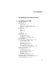
Contents 1 Storage Management Software Overview 2 Storage Manager on ROM Overview 2-2 Keyboard Reference 2-3 Menu Control 2-3 Left Pane – Tree View Control 2-4 Right Pane – Information View Control 2-4 Menu Reference 2-4 File 2-4 RAID 2-5 Action 2-5 Help 2-5 Icon Reference 2-6 Screen Layout 2-6 The Menu Bar 2-7 The Left Pane – Tree View 2-7 The Right Pane – Information View 2-8 Running SMOR 2-9 Information and Configuration Views 2-10 Controller BIOS Settings 2-10 Information Tab 2-13 Configuration Tab 2
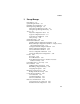
Contents 3 Storage Manager Introduction 3-2 System Requirements 3-3 Installing Storage Manager 3-4 Running Storage Manager 3-5 Using Storage Manager Locally 3-6 Using Storage Manager Remotely 3-6 Views 3-6 Physical Configuration View 3-6 Logical Configuration View 3-8 Logical Device Addresses 3-10 Array Groups 3-12 Status Reporting 3-23 Information Windows 3-24 Host Bus Adapter Information Window 3-24 Battery Backup Configuration Window – Adaptec 3200S/ 3210S/3400S/3410S Only 3-26 Configure Host Bus Adapt
Contents 4 RAIDUTIL Command Line Utility Introduction 4-1 Exit Status 4-2 Device Address Syntax 4-2 Command Line Switches 4-3 Miscellaneous 4-4 Logical Drive Creation and Deletion 4-4 Array Modification 4-6 RAID Operation 4-7 Controller-Specific 4-8 Hot Spare Control 4-9 General Information and Feedback 4-10 A SNMP Introduction A-1 Management Information Base A-2 Management Console A-2 Adaptec MIB Information A-3 SNMP A-5 What’s Included A-5 System Requirements A-6 Management Consoles A-6 Installing Ada
1 Storage Management Software Overview Your Adaptec RAID controller includes the following software tools to manage your storage subsystem: ■ Storage Manager Pro—The graphical user interface (GUI) through which you interact with the storage subsystem. It provides an intuitive graphical interface that enables you to do such things as create and manage RAID arrays, set up security levels for users and administrators, establish the means of notifying users of disk failures, etc.
Storage Management Software Overview ■ Storage Manager—Older storage management software that provides the same basic functionality as Storage Manager Pro but has the advantage of supporting the following additional operating systems: ■ SuSE Linux 6.4 and 7.0 ■ SCO UNIX/Unixware Furthermore, Storage Manager provides additional features, such as DMI agents, that are not yet available in Storage Manager Pro.
2 Storage Manager on ROM In this Chapter ➤ Overview ➤ Keyboard ➤ Menu ➤ Icon 2-2 Reference Reference Reference ➤ Screen Layout ➤ Running SMOR ➤ Information ➤ Setting ➤ Array and Configuration Views the Configuration Operations 2-3 2-4 2-6 2-6 2-9 2-10 2-25 2-26 ➤ Formatting a Drive – SCSI only 2-31 ➤ Upgrading Firmware – Flash HBA Option 2-32 ➤ Creating a SMOR Boot Disk 2-34 2-1
Storage Manager on ROM Overview Storage Manager on ROM (SMOR) is a BIOS-based setup utility that enables you to configure your Adaptec RAID controller without loading an operating system and using Storage Manager. You can also use SMOR to perform basic array configuration. SMOR makes the initial setup of your RAID controller and RAID storage easier and faster. To configure your hardware and create disk arrays when Storage Manager is not available, run SMOR during system startup.
Storage Manager on ROM 3 Create disk arrays (see Array Operations on page 2-26). Array groups can be created or modified at any time after system installation. However, if the boot device will be an array, that array must be created before the operating system is installed. 4 Exit SMOR when you are finished with the configuration tasks. Arrays that were created or modified start building at this time. For large arrays, this process may take several hours.
Storage Manager on ROM Left Pane – Tree View Control Up/Down Arrows Move between elements within the tree. Left/Right Arrows Scroll the tree left and right. + Expand the current branch, showing the devices attached to it. The element must be preceded by a plus sign. – Collapse the current branch. The element must be preceded by a minus sign. Tab Move to the right pane, Information View.
Storage Manager on ROM RAID Create… Create a new array. Delete Delete the currently selected array. Rebuild Rebuild a RAID 1, 5, 0/1 or 0/5 array. Stop Build Stop building or rebuilding an array. Action Make Hotspare Designate the currently selected drive as a hot spare. Remove Hotspare Make the currently selected hot spare available for use by the operating system. Format Drive (SCSI only) Low-level format a currently selected drive.
Storage Manager on ROM Icon Reference SMOR uses the following icons in the Tree View: HPT370 HPT370 · Controller Hard drive CD Array Tape Other Device Screen Layout The SMOR interface works like the Windows Explorer treestructured interface. The screen, shown in Figure 2-1, is divided into three major components: a menu bar across the top of the screen and two display panes below the menu bar. Information & Configuration Tab Pages Menu Bar Tree View Figure 2-1.
Storage Manager on ROM The Menu Bar To open a specific menu, press Alt+highlighted letter of the menu name. After a menu is open, you can select a specific menu item by pressing the key for the letter highlighted on the menu item. For example, to select the Read System Config item on the File menu, press Alt+F to open the File menu, then press R to select Read System Config. Note: Depending on your configuration, not all menu items may be available. Unavailable menu items are shown in a low-contrast color.
Storage Manager on ROM The Right Pane – Information View To the right of the component tree is the Information View pane. This area displays information related to the currently selected item in the tree. The specific information displayed in the Information View varies depending on the item selected. When there are separate types of information available for the selected item, the Information View is separated into tab pages.
Storage Manager on ROM Running SMOR Start SMOR by pressing Ctrl+A when the RAID controller BIOS message appears on the screen during the boot sequence. SMOR starts by displaying its opening screen, as shown in Figure 2-2 (showing the opening screen from a 2400A). Figure 2-2.
Storage Manager on ROM Information and Configuration Views When you highlight an item within the Tree View, the corresponding Information View is displayed. Controller BIOS Settings The controller displays the default Information View when SMOR starts, as shown in Figures 2-3 and 2-4. Figure 2-3. Configuration Window – ATA File RAID Action Help Configuration Local #0 2100S + + (0,0,9,0) RAID–1 + (0,0,12,0) RAID–5 SmartROM Configuration Bootable Devices [ ] Enable Bootable CD-ROMs DOS/Windows 3.
Storage Manager on ROM The settings in this view affect the controller BIOS and all the Adaptec controllers in your system. To view or change these settings, highlight Configuration in the Tree View. The following table illustrates the default settings to be found in the windows shown in Figures 2-3 and 2-4. Controller Options Default Available Settings Enable Bootable CD-ROMs Disabled Enabled DOS/Windows 3.
Storage Manager on ROM Scan Delay (SCSI only) Some devices require a time interval between power on, bus reset, and scan or they do not respond correctly. If devices are not displayed in the Tree View after power on, set the delay to a longer interval. EBDA Relocation This setting determines the way that RAID controllers handle Extended BIOS Data Area (EBDA) relocation.
Storage Manager on ROM Information Tab To view or change the configuration of the controller, highlight the controller in the Tree View. Available tabs are Information and Configuration, as shown in Figures 2-5 and 2-6. Figure 2-5.
Storage Manager on ROM The Information tab for a controller displays general information reported by that controller. Fields may have special conditions: Model Controller model number Serial # Controller serial number NVRAM Ver.
Storage Manager on ROM Configuration Tab The Configuration tab for a controller displays internal settings for that controller, as shown in Figures 2-7 and 2-8. Figure 2-7. Configuration Tab – ATA File RAID Action Help Configuration Local #0 2100S + + (1,1,9,0) RAID–1 + (1,1,12,0) RAID–5 I nf ormation Configuration Mem Address: IRQ: 11 ( ) Edge [ 3 ] PCI MWI Enable [ ] B oot Enable D8000000 ( ) L evel Default [ ] Cluster Server Enable Figure 2-8.
Storage Manager on ROM Select Default to reset the parameters on this tab to their default values. Mem Address, IRQ The values in the Mem Address and IRQ fields may be needed when you configure your operating system. These fields are read only. PCI MWI Enable Do not change this setting unless instructed to do so by Technical Support.
Storage Manager on ROM Bus Configuration Tab This tab enables you to modify the hardware parameters for the highlighted controller bus; it appears when you highlight a device in the Tree View, as shown inFigures 2-9 and 2-10. Figure 2-9.
Storage Manager on ROM Select Default to reset the parameters on this tab to their default values (SCSI only). Controller Parameter Default Available Settings ID 7 SCSI: 0 – 6 ATA: not shown Type As reported N/A Width As reported N/A Transfer Rate Maximum allowed for the controller Ultra3, Ultra2, Ultra, 10, 8, 5 Asynchronous Termination Auto On, Off, High Only TERMPWR On Auto, Off Note: As reported means that the field displays the value returned by the controller firmware.
Storage Manager on ROM Transfer Rate (SCSI only) The controller automatically negotiates with each device at powerup or reset to set the maximum transfer rate. This parameter limits the transfer rate to the value selected. This setting should not be changed except when you are troubleshooting bus errors. Note: On buses, if setting this parameter to 5 MHz eliminates bus data errors, this is usually an indication that the bus is too long or that the bus is not terminated correctly.
Storage Manager on ROM Device Information Tab Individual devices are listed in the Tree View under the controller to which they are connected, as shown in Figures 2-11 and 2-12. Highlight a device to view its information tab page. Figure 2-11.
Storage Manager on ROM The Device Information tab displays general information and configuration. This view is divided into either two or three parts: Description , SCSI Capabilities (for SCSI based RAID controllers only), and Status. The Description section displays a general description of the highlighted device, as follows: Description Manufacturer name and model number as reported by the device, followed by the icon for the device. Revision Device firmware revision.
Storage Manager on ROM The status condition is one of the following for attached devices: Dead Device failed to respond to controller commands. If the device becomes available, it only changes status after the system configuration is read or the host is restarted. Failed Drive failure occurred. Impacted Performance degradation in response to server I/O requests. Missing Drive is physically missing or does not respond to commands on the device bus. Optimal Device is fully functional.
Storage Manager on ROM Array and Array Group Information The Information tab for any array may be viewed by highlighting that array, as shown in Figures 2-13 and 2-14. Figure 2-13.
Storage Manager on ROM RAID 0 arrays are comprised of any number of drives greater than 1. RAID 1 arrays are comprised of multiple pairs of drives. RAID 5 arrays contain three or more drives. After you create the arrays, one or more arrays of the same RAID level can be combined into a multilevel RAID (see Creating a Multilevel RAID on page 2-28). Arrays are striped into multilevel RAIDs by the controller firmware.
Storage Manager on ROM The Status section displays the current status of the array. A progress indicator (a numeric percentage of completion) can also appear if the array is building or rebuilding. The status definitions are listed below: Building The array is being built. Created The array or device is defined, but not initialized. Dead A Write Back Cache command to the array failed. This is an unrecoverable failure. Degraded A single drive in the array failed; array performance is degraded.
Storage Manager on ROM Array Operations This section describes how to use SMOR to create arrays and multilevel RAIDs, delete arrays, assign hot spare drives, and rebuild an array. Creating an Array To create an array, follow these steps: 1 Select RAID > Create. The RAID Type window appears as shown in Figure 2-15.
Storage Manager on ROM a When you are ready to proceed, select Ok. b The Eligible Devices tab appears, as shown in Figure 2-16. The list of eligible devices can be either individual hard drives or previously created array groups. Array groups appear in the list when you select RAID 0 and eligible array groups exist.
Storage Manager on ROM 5 If you are creating a RAID 1 array, the RAID 1 Build Option window appears, as shown in Figure 2-17. RAID 1 arrays are built by copying the existing data from one device to the other. Select the direction for the copy, then select Ok. RAID 1 Build Option: ( ) Copy from (1,2,0,0) to (1,0,12,0) ( ) Copy from (1,0,12,0) to (1,2,0,0) Ok Cancel Figure 2-17. RAID 1 Build Option Window 6 Select File > Set System Config to start the build process.
Storage Manager on ROM 3 Select RAID 0 for the RAID type and click Ok. 4 Select two or more arrays of the same type from the list of eligible devices, then click Done. Note: You cannot combine arrays that use different RAID levels. 5 Select File > Set System Config to begin the build process for the multilevel RAID. The Tree View displays the multilevel RAID LSU as (x,x,x,x) FW RAID-0 with the array groups listed where drives would normally be listed.
Storage Manager on ROM Hot Spares Hot spares automatically replace failed drives in protected arrays and are not accessible by the operating system for other use. Any hard drive not assigned to an array or in use by the operating system can be designated as a hot spare, as long as the spare drive is at least as large as the other drives in the array. To assign a drive as a hot spare, follow these steps: 1 Highlight the drive you want to use in the left pane. 2 Select Action > Make Hotspare.
Storage Manager on ROM Rebuilding a Failed Array To replace a failed drive in an array that is not protected by an automatic hot spare, follow these steps: 1 Remove and replace the failed drive according the procedures in your hardware documentation. 2 When the failed drive has been replaced, select RAID > Rebuild Array to start the rebuild process. The status of the array changes to Rebuilding (view the Information tab for that array).
Storage Manager on ROM Upgrading Firmware – Flash HBA Option The firmware on your controller is upgradable using the Flash HBA option, which appears on the Action menu when a controller is selected in the Tree View. The Flash HBA option enables you to upgrade to the latest firmware, controller BIOS and SMOR. Note: There is no way to backup the controller firmware. When you upgrade to the latest firmware, the previous firmware image is replaced by the new one and any settings you may have made are lost.
Storage Manager on ROM 4 Select Action > Flash HBA. The Source File Browser window appears, as shown in Figure 2-19. -A: - 2 100320B.IMA I 2OBIOS.134 S MOR0031.112 #0 2 100S: Select a source for flash image using the browser. Select OK button to start flash procedure. Ok Cancel Figure 2-19. Source File Browser Window 5 In the Source File Browser window, select the hard drive that contains the image files. Press Enter to expand the drive listing.
Storage Manager on ROM Creating a SMOR Boot Disk To create a SMOR boot disk, click Action > Make Boot Floppy or use the Adaptec RAID Installation CD. You may need a SMOR boot disk in certain situations when it is not possible to access SMOR by typing Ctrl+A during startup. To create a SMOR boot disk 1 Insert a blank disk into the disk drive. 2 Select Action > Make Boot Floppy. 3 When prompted, select Yes to create the bootable disk.
3 Storage Manager In this Chapter ➤ Introduction 3-2 ➤ System 3-3 Requirements ➤ Installing ➤ Running Storage Manager 3-4 Storage Manager 3-5 ➤ Views ➤ Status 3-6 Reporting ➤ Information Windows ➤ Events Drives – SCSI only Failures ➤ Running a Verify Process ➤ Controller ➤ Remote 3-24 3-35 ➤ Formatting ➤ Drive 3-23 3-44 3-45 3-48 I/O Statistics 3-49 Communication 3-54 3-1
Storage Manager Introduction Adaptec’s Storage Manager gives you complete control over your storage subsystem, enabling you to manage your storage locally or remotely across a network. Storage Manager enables you to check your device configuration, configure your controller, create and manage your disk arrays, and provides online event logging and performance statistics.
Storage Manager System Requirements Adaptec Storage Manager software and device drivers require approximately 4 MB of disk space. The host system should have at least 64 MB of memory and a Pentium processor (200 MHz or faster). A mouse and SVGA color monitor are required. The host system should comply with the PCI Local Bus Specification (revisions 2.1 and 2.2) and must be able to roperly configure multifunction PCI devices where one of the devices is a bridge.
Storage Manager Installing Storage Manager The original installation of the software starts with the installation instructions covered in chapter 4 of the Adaptec RAID Installation Guide. Use the instructions appropriate for the operating system being used. On operating systems other than Windows, Storage Manager would have been installed during the process of copying the files from the CD to the areas denoted in the installation instructions.
Storage Manager . Figure 3-1. Storage Manager Setup Window Running Storage Manager You can run Storage Manager in one of the following ways: ■ Locally—On the same computer that contains the RAID controller and drives. ■ Remotely—Across a TCP/IP network, you can view and configure servers from remote locations. Using Storage Manager Locally Storage Manager scans for RAID controllers installed on the computer on which it is run.
Storage Manager Views This section describes the two primary configuration views, which are: ■ Physical Configuration View ■ Logical Configuration View (includes Logical Device Addresses) Physical Configuration View The first window displayed by Storage Manager is the Physical Configuration View (see Figures 3-2 and 3-3). This window displays each RAID controller in the system along with the peripheral buses and attached devices.
Storage Manager Figures 3-2 and 3-3 show sample views of Physical Configurations. Figure 3-2. Physical Configuration Window – ATA Figure 3-3.
Storage Manager Logical Configuration View On the right side of the Logical Configuration View Window, shown in Figures 3-4 and 3-5, are all the physical devices that are attached to the RAID controllers. Figure 3-4. Logical Configuration Window – ATA Figure 3-5.
Storage Manager On the left side of the window are the associated logical devices as seen by the host computer. Storage Manager displays the same icon for non-hard-drive devices in both logical and physical views. Hard drives appear either as individual drives or as members of arrays. In either case, the drive or array is represented on the left side of the window as a Logical Storage Unit (LSU).
Storage Manager Logical Device Addresses Every device and array is assigned a logical device address by Storage Manager. This is the address used by the host operating system to access the device or array. Logical device addresses appear in parentheses under the logical device and LSU icons on the Logical Configuration View window. Figures 3-6 and 3-7 show typical LSU numbering, array numbering, and drive numbers. Figure 3-6. Logical Device Addressing – ATA Figure 3-7.
Storage Manager The complete logical device address is composed of the following fields: HBA The controller to which the device is attached. PCI bus slots are scanned from lowest to highest looking for Adaptec controllers. As Adaptec controllers are found, they are assigned numbers incrementally, starting with 0. Bus Channel number of the channel to which the device is attached. LUN The LUN for that device is normally 0. Device The unique ID for that device.
Storage Manager Array Groups The tool bar at the top of the Logical Configuration View window, shown in Figures 3-4 and 3-5, contains the following buttons: Switch View Switches to the Logical Information View. For more information, see page 3-21. Create Array Group Starts the process of collecting available individual drives to assemble into a RAID array. For more information, see page 3-16.
Storage Manager Although arrays must be built from drives that are all attached to the same controller, arrays can contain drives from multiple channels. The approach is slightly different for each controller model: Adaptec 2400A Supports one drive per channel, for a total of four drives; therefore, any RAID array involves spreading the drives across channels. Adaptec 2100S Provides a single channel with support for up to 15 devices.
Storage Manager To view the Array Group Information window, shown in Figures 3-8 and 3-9, double-click the appropriate array icon in the Logical Configuration View window. Figure 3-8. Array Group Information Window – ATA Figure 3-9.
Storage Manager The Array Group Information window displays the following information: Name The descriptive name assigned to the array. An icon in the upper right corner of the window indicates the RAID level. Address This is the logical device address used by the host operating system to access the logical drive. The address is the same as the lowest device address in the array. Capacity The total usable storage capacity of the array in MB.
Storage Manager Name Allows entering or changing the name to be shown for this RAID array. This does not affect the LSU of the array. For more information, see page 3-23. Configure Allows changing the configuration of the array. Print Prints the configuration file of the selected RAID array. Build Arrays that have a build pending display this button. Rebuild Redundant arrays that have a failed drive show this button. Stop Bld Arrays that are building or rebuilding show a Stop Bld button.
Storage Manager 4 As you make your selections, the Chosen Array Parameters change to indicate which RAID level and stripe size best fit your selection. 5 You can customize the RAID level and stripe size defaults by selecting the Override button. 6 Click Continue to select the drives you want to use. The Logical Configuration View window appears with the caption Choosing Drives for Array (RAID n), where n is the RAID level chosen.
Storage Manager 8 When you are finished creating arrays, exit Storage Manager. You are prompted to save the configuration changes. If you save the configuration, the build operation starts automatically. If you have created multiple arrays, they are built one at a time in the order created. You can also start the build without exiting Storage Manager by selecting File–Set System Configuration. Note: The array initialization process can take several hours to complete.
Storage Manager If you want to monitor the progress of the build operation, display the Array Group Information window for the new array group. The build progress is displayed as a percentage of completion in the Status field. You can also view the Information window for an array that is a member of a multilevel RAID to monitor the progress for that component of the multilevel RAID.
Storage Manager The array expansion feature enables you to add the new drives to the array while the system is active and users are logged in and accessing data. After the array is expanded, use the Windows Disk Administrator to add the additional space to the volume set of the array, then shutdown the system and restart. When the system restarts, Windows recognizes the additional space as part of the existing logical drive. Note: Array expansion significantly reduces overall system performance.
Storage Manager ■ Each new drive added to an array must be at least equal to the capacity of the smallest capacity drive already in the array. This is because in any RAID configuration, the drive with the least capacity in the array determines the usable capacity of all the drives in the array. There is no advantage in adding a drive with a capacity larger than the smallest capacity drive already in the array.
Storage Manager 8 Select File–Set System Configuration to start the array expansion. The status flag on the array group turns blue and the flags on the components turn white during the expansion process. You can perform other activity on the system while the expansion continues, because the array is fully functional during the expansion process. For large arrays, the expansion can take several hours to complete. Host I/O activity can prolong the expansion process.
Storage Manager Use the rdisk.exe utility to update your emergency repair disk with the new disk configuration information. Deleting an Array Group To delete an array group, follow these steps: 1 From the Logical Configuration View window, select the LSU or array group icon of the array you want to delete. Then, select Delete Array Group. 2 Select OK when the confirmation message appears to complete the delete operation. Click Cancel to exit without deleting the array group.
Storage Manager Pending The array has been created and the build is queued on the controller, but is not yet started. Rebuilding Data is being rebuilt onto a drive in the array.
Storage Manager The Host Bus Adapter Info window (ATA and SCSI) displays the current bus configuration. Figure 3-12. Host Bus Adapter Info Window – ATA and SCSI Note: The RAID controller requires 16 MB of memory for its operation. The available cache memory reported here equals the amount of memory installed minus 16 MB. The following buttons are available: Configure Examine and change HBA parameters, or download new firmware code. For more information, see page 3-27.
Storage Manager Battery Backup Configuration Window – Adaptec 3200S/ 3210S/3400S/3410S Only This option enables you to view the status of the battery backup module, as shown in Figure 3-13, and set operating parameters when the battery capacity reaches a predetermined level. The battery status and available backup capacity (in hours) is displayed.
Storage Manager Configure Host Bus Adapter Window Click Configure in the Host Bus Adapter Info window to modify hardware parameters for the RAID controller, The Configure Host Bus Adapter window appears, as shown in Figures 3-14 and 3-15. Figure 3-14 shows a four-channel RAID controller. Figure 3-14. Configure Host Bus Adapter Window – ATA Figure 3-15.
Storage Manager The following buttons are available: Test Alarm (SCSI only) Tests the audible alarm on the controller. Flash Displays the Flash Configuration window to update the controller firmware and BIOS. Caching Selects the controller cache parameters. Defaults Resets the controller configuration to factory default settings. Cancel Cancels any changes you have made and returns to the Host Bus Adapter Info window. SCSI ID (SCSI only) Your controllers is set to ID 7 by default.
Storage Manager Controller Caching – Windows NT only To ensure optimum performance, follow these steps: 1 Click Caching in the Configure Host Bus Adapter window to display the HBA Caching Configuration window. 2 When the HBA Caching Configuration window appears, change both of the settings to Advisory. The Advisory setting allows the controller to use its own algorithms for cache management. This is more efficient than allowing the operating system to direct the cache operation.
Storage Manager Figure 3-16. Flash Configuration Window – ATA and SCSI The current controller model, firmware version, and firmware type are displayed. To specify an image file for the flash operation, you can type a path and filename in the Filename field or click Browse to use a file selection window. Firmware images are contained in a xxxxxxxx.ima file, where the 8-character file name consists of the 4-digit model number and a 4-digit release number.
Storage Manager Device Information Window The Device Information Window is shown in Figures 3-17 and 3-18. Figure 3-17. Device Information Window – ATA Figure 3-18.
Storage Manager The Device Information window displays the following information: Description The manufacturer and model. Revision The drive firmware revision. Address The logical address of the device. Capacity Storage capacity of the device in MB. For removable-media devices, capacity is reported for the currently inserted media. Sectors Total number of sectors on the drive. SCSI devices may refer to sectors as blocks in some other reference material. Bytes/sector Sector size (always 512).
Storage Manager Device Configuration Window Click Configure in either Device Information or Array Group Information window to display the Device Configuration window, shown in Figure 3-19. Figure 3-19. Device Configuration Window – ATA and SCSI The Device Configuration window enables you to change the caching parameters for your controller and provides the following: Predictive Cache Enables and disables the predictive caching feature on RAID controllers. This feature is disabled by default.
Storage Manager Write-through Writes all data to disk for each Write command before Command Complete status is returned to the host. The data can also be cached for subsequent read commands. Defaults Click to revert to the default setting. Cancel Click to exit this window without saving changes. OK Click to exit with changes. Saving the Subsystem Configuration The Storage Manager File menu has the following options: Read System Configuration Reads the current hardware configuration.
Storage Manager Events Events are generated for detected fault conditions as well as RAID status changes, and are described as follows: Soft Error An operation on a hard drive that caused an error, but was successful after a retry. Recoverable Hard Error An error on a hard drive, controller, or peripheral bus, where the data was recovered using ECC or from redundant array information.
Storage Manager When the Event Log button is selected, the Event Logs window appears, as shown in Figure 3-20. Figure 3-20. Event Logs Window The Event Logs window enables you to limit the display to a specific level or higher (the default is level 4). Note: Some important events may not be displayed by the default level. You should select one of the higher event levels to ensure displaying significant errors.
Storage Manager Note: Only the event messages that appear on the screen when you click Print are printed. Therefore, if you want to print specific messages, scroll the list until the messages are visible and then click Print. Event Broadcaster If your operating system supports a broadcaster, Storage Manager enables you to specify that event messages be sent to users, groups, and devices, through email, to the system error log, and the Adaptec log file.
Storage Manager You can select or modify the following parameters: Time Interval Interval at which the broadcaster reads the controller event logs. Broadcast to Computer(s) When enabled, event messages are sent to each system in the Computer Names list. Local Desktop Message When enabled, event messages are displayed on the local system desktop. Email to users When enabled, event messages are e-mailed to each address in the Email Users list.
Storage Manager Windows NT & Windows 2000 The broadcaster collects events from the controller and records them to files in the c:\program files\adaptec\storage manager folder for use by Storage Manager. Additionally, events are sent to the Windows Event Viewer or e-mailed as specified in the Event Broadcasting window.
Storage Manager This window displays a list of the events submitted to the application log by the broadcaster, as well as other applications. Adaptec events are single-line entries that contain the following information: Icon Indicates the severity of the event. Levels are Error, Warning, Information, Operation, or Unknown. Date Date the event was logged by the controller. Time Time the event was logged by the controller.
Storage Manager NetWare The broadcaster collects controller events and records them to files in the sys:\system\dpt directory for use by Storage Manager. Additionally, events are broadcast to the system console, the system error log file, or to users as specified in the Storage Manager Event Broadcasting window. If a you want to receive broadcast messages from the broadcaster module (dptnwmsg.
Storage Manager SCO UNIX The broadcaster collects controller events and saves them to files in the /usr/dpt directory for use by Storage Manager. Events can also be sent to an ASCII file, specified devices, or e-mailed as specified in the Event Broadcasting window. Installing the Broadcaster When you install the controller driver, you automatically install the the broadcaster in /usr/dpt.
Storage Manager Event Messaging by Pager – Windows 2000 and Windows NT only Storage Manager can send event messages by e-mail to alphanumeric paging devices. Note: This feature should work with any alphanumeric paging system that supports email. Contact your service provider for specific information. To configure alphanumeric pager support, follow these steps: 1 Ensure your pager is working and activated by a service provider.
Storage Manager Formatting Drives – SCSI only Your controller can perform a low-level format on attached hard drives in standard 512-byte format. This function is available from the SCSI Device Information window. A low-level format is not normally required before using a hard drive. However, if a drive has been previously formatted with a different sector size, it must be reformatted with 512-byte sectors before it can be recognized by the controller.
Storage Manager Drive Failures Drive failures are indicated by flags, which differ depending on whether they refer to an array or a drive in an array. Failure conditions are indicated as follows: Device Type Individual Drive Individual Drive Array Type None 0 Individual 1, 0/1, 5, Drive or 0/5 Flag in Flag in Physical Logical Configuration Configuration Probable cause Red Red Black Black Drive is either missing or has stopped responding.
Storage Manager Rebuilding a Degraded Array When a drive in an array fails, and that drive is not protected by an automatic hot spare, the array can be restored to Optimal status. Note: You can select Rebuild even if the failed drive has not been replaced and try using the drive again. If the rebuild attempt is not successful, replace the drive before starting another rebuild. To rebuild an array, follow these steps: 1 Replace the failed drive according to the procedure in your hardware documentation.
Storage Manager Assigning Hot Spares To assign a drive as a hot spare, click Make Hotspare in the drive’s Device Information window. Click Remove Hotspare to reassign an existing hot spare drive as a normal drive. You should reboot your operating system to ensure that the hot spare drive is recognized correctly. Hot spares are reserved to automatically replace failed drives in RAID 1 or 0/1 and RAID 5 or 0/5 arrays and cannot be accessed by the operating system for data storage.
Storage Manager Running a Verify Process Running a manual Verify for a RAID array ensures that the redundant information contained in the array is consistent. Note: Data inconsistencies should not occur under normal conditions. However, a power failure that interrupts an array write operation can cause inconsistencies. Making the data consistent again through the Verify function does not ensure that the new consistent data is the correct data.
Storage Manager Select Options > Background Task Priority to control the relative priority of I/O from the operating system and background tasks. Figure 3-22 shows the Background Task Settings window. Figure 3-22. Background Task Settings Window – ATA and SCSI The Priority section assigns the controller background task priority. Set the task priority by using the arrow buttons to move the indicator. The indicator moves between Background and Foreground in ten increments.
Storage Manager To see the HBA statistics window, shown in Figures 3-23 and 3-24, click I/O Stats in the Host Bus Adapter Info Window. Figure 3-23. HBA Statistics Window – ATA Figure 3-24.
Storage Manager Cache Statistics Total Pages The total number of pages contained in the controller cache. Used Pages The number of pages that currently contain disk data. Dirty Pages The number of pages that contain dirty data (data that requires correction). Read-Ahead Pages The number of cache pages that contain data that has been loaded from disk as a result of read-ahead functions.
Storage Manager This is because each sector written from the host results in a write to each mirrored disk. In RAID 5 arrays, each write from the host can generate up to two disk reads and two disk writes. Because the controller has cache memory, the reported number of sectors read from or written to disk may be less than this value. I/O statistics are displayed in the Hard Drive I/O Statistics window, as shown in Figure 3-25. Figure 3-25.
Storage Manager Cache Misses The total number of sectors that were not accessed from the controller cache, thus were read directly from the disk. Read-Ahead Hits The number of the cache hits for data read requests satisfied by data held in the cache from previous disk read-ahead operations. Write-Backs The number of sectors written to disk that were held in the controller cache and written some time after the host Write command reported as completed.
Storage Manager Remote Communication The Storage Manager Remote Communication feature enables you to use Storage Manager running on your local workstation to manage remote server system with a RAID controller. The Available Connections window (shown in Figure 3-26) shows the types of connections you can use and any predefined connections you have created. Figure 3-26.
Storage Manager Connecting Across a Network Storage Manager can run as a client/server application across a network using a TCP/IP connection. The Storage Manager client runs on a supported workstation operating system and connects to one of the supported networked servers running the Adaptec communication engine. Figure 3-27 shows the supported workstation and server connections for a TCP/IP network.
Storage Manager You must configure remote communication before it can be used. For both workstations and servers, this is done by editing the Storage Manager configuration file (dptmgr.ini). There may be additional server configuration steps, depending on your operating system. You must have physical connections between the servers and client workstations. Note: Under Windows 95/98/Me, the server must be started manually by selecting the Adaptec Communication Server icon.
Storage Manager The following list shows all supported options. The value listed is the default; optional values are in parentheses. [TCP] TCP/IP protocol. SOCKET=2091 TCP socket on which to listen. Can be any valid socket number. Setting up the Server If you are using an operating system that supports the Adaptec communication server and selected the Communication Server option during Storage Manager setup, the server was automatically installed at that time.
Storage Manager Windows 95/98/ME The communication server is installed as a DOS command line application. To start the communication server, double-click Start > Storage Manager > Communication Server. To access the server, you need a password only; a user name is not required. The initial default password is password. To change the password, click Start > Storage Manager > Change Communication Password. Novell NetWare Logging in to a NetWare server requires a user name and password.
Storage Manager Linux The Linux communication server is installed if the option is selected during the Storage Manager software install process. The server module is copied to /usr/dpt and loads automatically. A valid user name and password are required to access a Linux system from a remote Storage Manager client. The user ID must have root privileges on the host system. FreeBSD The FreeBSD communication server is installed if the option is selected during the Storage Manager software install process.
Storage Manager Figure 3-28. Available Connections Window From this window, you can make a connection either by selecting one of the available protocols under Manual Connections and entering the name, address, and password of the server; or by selecting an entry under Custom Connections. Custom Connections are those for which you previously stored address information in the Phonebook (see Using the Phonebook on page 3-62 for more information).
Storage Manager Making a Manual Connection In the Manual Connections section of the Available Connections window, there is one icon for each protocol that you configured in the dptmgr.ini file, and an icon for the system you are using (Local). To make a connection to a remote system, double-click the icon that represents the protocol that your workstation uses to connect to that system. (To select the system from which you are running Storage Manager, select the Local icon).
Storage Manager Using the Phonebook You can save the server name, address, user name, and protocol of systems you frequently access in the Phonebook, shown in Figure 3-30. After you have entered data for a system, you can place an icon under Custom Connections to make future connections to that system without having to re-enter the connection information each time. To make an entry in the Phonebook, fill in the appropriate fields. Figure 3-30.
Storage Manager Using a Custom Connection Under the Custom Connections section of the Available Connections window, there is one icon for each system that you marked for display in the Phonebook. To make a connection to a remote system, double-click the icon. The Connection Information window appears, as shown in Figure 3-31. Enter the password of the server selected. Refer to Connecting Servers and Workstations on page 3-59 for details. Figure 3-31.
4 RAIDUTIL Command Line Utility In this Chapter ➤ Introduction 4-1 ➤ Command 4-3 Line Switches Introduction The command line utility (RAIDUTIL) performs operations as soon as it has enough information from the command line to do so. The utility does not parse the entire command line before starting an operation. Operations are performed in series up to the first failure encountered. If the utility does not have all of the information necessary when it attempts to perform an action, reports an error.
RAIDUTIL Command Line Utility Exit Status RAIDUTIL exits with either of the following error status indications: 0 Error-free termination 1 Error termination (the message log contains the error information) Device Address Syntax When you use RAIDUTIL to specify a device or group of devices, use an address of the form dDbBtTdD, where D Controller ID. B Controller channel (or bus) number of the bus to which the disks are attached. The range is 0 – 7. T Always 0. D the second “D”—Always zero.
RAIDUTIL Command Line Utility Command Line Switches Following is a list of the switches available in RAIDUTIL for testing and controlling various aspects of the controller, arrays, and drives attached to the controller.
RAIDUTIL Command Line Utility Miscellaneous -g Specify drive group This switch identifies the physical drive to be used for array creation, deletion, or modification. It must always be the last switch in the array creation command sequence and it must always be followed by a drive address as discussed in Device Address Syntax on page 4-2. Multiple drive addresses on a command line must always be separated by commas.
RAIDUTIL Command Line Utility -D Delete logical drives This command deletes the specified drives and returns their capacity to unassigned space. If all is specified, then all logical drives on the controller are deleted. Logical drives are specified by the device address. Use commas to separate drive addresses. If Quiet (-q) mode is not used, a confirmation message is displayed.
RAIDUTIL Command Line Utility -z Specify logical drive stripe size Specifies the stripe size (in KB) for new RAID 0 and RAID 5 logical drives. Valid stripe sizes are: 8, 16, 32, 64, and 128 (KB). This switch is ignored for RAID 1. If omitted, a default stripe size is used. The default is selected by the controller firmware based on the number of drives in the array.
RAIDUTIL Command Line Utility RAID Operation -C Load/save configuration This switch has two options: load Loads the specified configuration file save Saves the current configuration to the file name specified A file name must follow the load or save parameter. This is a .dsm file, which can also be loaded or saved using Storage Manager. -r Specify task rate This switch sets a task priority for the device or logical drive.
RAIDUTIL Command Line Utility Controller-Specific -a Action (task) control This switch has the following options which allow you to control tasks on the controller: List Shows tasks for the controller Build Starts build of logical drive Rebuild Starts rebuild on logical drive Verify Starts a verify operation Stop Terminates active task on drive Specify drives by the device address. -F Update controller firmware, BIOS, or NVRAM This option updates the controller flash memory (EEPROM).
RAIDUTIL Command Line Utility All specified drives become individual, unassigned physical drives after this command is used. ! Note: There is no procedure to reverse the effect of the -Z operation. This option is a method of last resort for deleting conflicting RAID table information. Hot Spare Control -h Create hot spare drive This switch creates one or more stand-alone hot spare drives. The drives must physically exist and may not contain any logical drive segments.
RAIDUTIL Command Line Utility General Information and Feedback -? Display utility usage information This option displays a summary of the command usage information. This includes all command line switches and brief definitions.
RAIDUTIL Command Line Utility -I Display inquiry information This switch displays controller specific information, including firmware revision, BIOS version, and serial number. Specify drives by the device address. -L List devices Specify drives by the device address. The parameters for this switch are listed below: Controller Displays a list of all Adaptec controllers in the system. Physical Displays all attached devices to the specified controller.
RAIDUTIL Command Line Utility -P Pagination output Limits output to 22 lines, then prompts to press Enter to continue. Pressing Enter prints another 22 lines. Use this switch to prevent lengthy output from -L from scrolling off the screen. raidutil -P -L All -q Quiet mode This switch suppresses display of messages while the utility is running. This can be useful when running it from a script or batch file.
A SNMP ➤ Introduction A-1 ➤ Management Information Base A-2 ➤ Management Console A-2 ➤ Adaptec MIB Information ➤ SNMP ➤ What’s A-5 Included ➤ System Requirements ➤ Management ➤ Installing ➤ SNMP A-3 Consoles Adaptec SNMP Support Architecture A-5 A-6 A-6 A-6 A-8 Introduction SNMP (Simple Network Management Protocol) is a group of network management specifications that includes the protocol itself, the definition of the database, and associated concepts.
SNMP Management Information Base As with any network management system, the core component of SNMP is the database containing the information about the objects to be managed. For SNMP this is referred to as the Management Information Base (MIB). A MIB is written using the ASN.1 (Abstract Syntax Notation One) format as described in ISO 8825-2.
SNMP Adaptec MIB Information The specific hardware and configuration information in the Adaptec MIB includes groups for the following: ■ Adaptec system modules ■ Adaptec controllers ■ Adaptec buses ■ Adaptec devices ■ Adaptec arrays ■ Adaptec statistics ■ Adaptec events Refer to the MIB itself for the exact contents of each of these groups.
SNMP ■ ■ ■ Host bus type ■ Max transfer rate ■ Controller modules (RAID, expansion, caching, DIMMs) Adaptec Bus group is a list of the buses with a set of parameters which describe and control a bus.
SNMP ■ Adaptec Statistics group contains statistical information regarding the Adaptec controllers, devices, and arrays. Each controller includes statistics on the following: ■ Cache pages ■ Commands ■ Transfers For devices and arrays there are statistics on the following: ■ Cache hits/misses ■ Stripe boundary crossings ■ Physical I/O commands (read/write) Adaptec Events group is used to send traps on controller event log entries.
SNMP The Windows components can be installed directly from the CD-ROM or a from a disk you create from the CD-ROM. The components are as follows: ■ Adaptec event logger ■ SNMP event logger extensions ■ Adaptec SNMP subagent ■ Adaptec MIB System Requirements The Adaptec SNMP software supports all Adaptec RAID controllers and has the following system requirements: ■ The TCP/IP network protocol must be enabled on your system.
SNMP The Adaptec SNMP software can be installed during the Adaptec Storage Manager installation process. The Setup utility displays a Select Components window that includes a check box for the Adaptec SNMP software. By default, this box is not checked. To install SNMP software, check the box labeled SNMP Agent. Continue with the installation according to the installation procedure for your operating system in the Adaptec RAID Installation Guide.
SNMP Installing the MIB Before you can view information about your controller, you must install the Adaptec MIB into the Management Console database. During the installation of the SNMP feature, the Adaptec MIB is installed by default in \program files\storage manager\dptscsi.mib Refer to your SNMP management console documentation for more information about adding this MIB to your existing database. The Adaptec SNMP subagent can be accessed from any SNMP Management Console.
SNMP The components used in the SNMP implementation are the Adaptec engine, broadcaster, and device driver. The Adaptec engine is used to gather all information on the system configuration and to perform the defined management functions. An SNMP trap broadcast module has been added to the event logger to handle messages that are intended specifically for the SNMP console.
B DMI In this Chapter ➤ Introduction B-1 ➤ System B-2 Requirements ➤ Adaptec CI ➤ Installing ➤ Adaptec B-2 DMI Support B-3 DMI Modules B-3 Introduction The Desktop Management Interface (DMI) is a standard developed by the Desktop Management Task Force (DMTF) to manage computer systems and their components locally or remotely. The DMTF has defined a mapping standard that allows SNMP and DMI components to work together. The Adaptec DMI component instrumentation conforms to the version 2.
DMI DMI consists of three components: ■ SP (Service Provider)—Manages the communication between the MA and the CI. Maintains a database of components that are defined by Management Information Format (MIF) files. ■ Management Application (MI)—The Management Application (MI) is the interface that allows a user to locally or remotely manage the components of a computer system.
DMI Adaptec CI At startup time the CI gathers information about Adaptec RAID controllers and stores this information in a DMI format table. When an inquiry is made for a particular attribute it is obtained from this table for static information or through the engine for dynamic information. The Adaptec CI sends event notification up to the SP for events that are reported by the broadcaster module. These events include high or low voltage, high temperature, drive failure, and RAID status changes.
DMI Installing DMI Support Adaptec supplies the CI only. The SP and MI must be provided by the operating system or other third-party. The CI consists of the Adaptec engine, broadcaster, controller driver, firmware, and CI module. The CI module is a separate add-on that is installed only if Storage Manager is already installed.
DMI The following is a list of groups contained in the Adaptec Mass Storage MIF file. For the attributes of each group, refer to the admpdmi.mif file.
© 2000, 2001 Adaptec, Inc. All rights reserved. Adaptec, and the Adaptec logo are trademarks of Adaptec, Inc. which may be registered in some jurisdictions. P/N: 512862-06, Ver.