
Installation guide

A-5
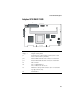
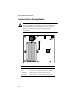
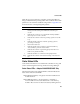
Card and Module Diagrams
Adaptec SCSI RAID 3400S
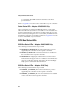
Part Description
ECCEN ECC enabled LED (green)
ECCERR ECC error LED (red)
IRQ, 8..1 Adapter activity LEDs
J1 Cache memory socket 1. (During operation, this socket
must contain a memory module.)
J2
Cache memory socket 2. (Memory is optional for this socket.)
J12 Battery module connector
P3 Pins 1–2 Retry
P1 PCI connector
P4 Pins 1–2 NVRAM reset
Pins 3–4 Reserved—do not use
P6 Hard drive activity LED connector. (Pin 1 is nearest the
top edge of board.)
P9 Flash Mode 0
TRMEN-A/B Termination-enabled status LED
TRMENHD-A Upper 8-bit termination status LED for Channel A
TRMPWR-A/B Termination power status LED
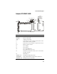
J1
J7
J14J10
P6P4
J11
J15
P3
P9
J8
J2
J12
Audible
Alarm
TRMEN-
B
IRQ
ECCERR
ECCEN
8 7 6 5 4 3 2 1
TRMENHD-A
TRMEN-A
TRMPWR-B
TRMPWR-A
PCI Connector