R P2B-D2 Dual Pentium II Motherboard ® USER’S MANUAL
USER'S NOTICE No part of this manual, including the products and software described in it, may be reproduced, transmitted, transcribed, stored in a retrieval system, or translated into any language in any form or by any means, except documentation kept by the purchaser for backup purposes, without the express written permission of ASUSTeK COMPUTER INC. (“ASUS”).
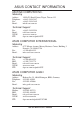
ASUS CONTACT INFORMATION ASUSTeK COMPUTER INC. Marketing Address: Telephone: Fax: Email: 150 Li-Te Road, Peitou, Taipei, Taiwan 112 +886-2-2894-3447 +886-2-2894-3449 info@asus.com.tw Technical Support Fax: Email: WWW: FTP: +886-2-2895-9254 tsd@asus.com.tw www.asus.com.tw ftp.asus.com.tw/pub/ASUS ASUS COMPUTER INTERNATIONAL Marketing Address: Fax: Email: 6737 Mowry Avenue, Mowry Business Center, Building 2 Newark, CA 94560, USA +1-510-608-4555 info-usa@asus.com.
CONTENTS I. INTRODUCTION .............................................................................. 7 How this Manual is Organized ........................................................... 7 Item Checklist ..................................................................................... 7 II. FEATURES ....................................................................................... 8 Features ...............................................................................................
CONTENTS Chipset Features Setup ................................................................ 48 Details of Chipset Features Setup .......................................... 48 Power Management Setup ........................................................... 51 Details of Power Management Setup .................................... 51 PNP and PCI Setup ..................................................................... 54 Details of PNP and PCI Setup ...............................................
FCC & DOC COMPLIANCE Federal Communications Commission Statement This device complies with FCC Rules Part 15. Operation is subject to the following two conditions: • • This device may not cause harmful interference, and This device must accept any interference received, including interference that may cause undesired operation. This equipment has been tested and found to comply with the limits for a Class B digital device, pursuant to Part 15 of the FCC Rules.
I. INTRODUCTION I. INTRODUCTION Manual / Checklist How this Manual is Organized This manual is divided into the following sections: I. II. III. IV. V. Introduction Features Installation BIOS Software Support CD Manual information and checklist Information and specifications Setting up the motherboard and jumpers Setting up the BIOS software Information on the included support software Item Checklist Check that your package is complete. If you discover damaged or missing items, contact your retailer.
II. FEATURES Features II. FEATURES Specifications The ASUS P2B-D2 motherboard is carefully designed for the demanding PC user who wants advanced features processed by the fastest CPU. • Multi-Speed: Supports Dual Intel Pentium® II processors from 233MHz to 450MHz. • I2O: Includes Intel’s i960RD I/O processor with 32KB NVRAM, 4x512KB Flash EEPROM, and 2 SIMM slots for up to 256MB of memory.
II. FEATURES The ASUS P2B-D2 Motherboard T: PS/2 Mouse B: PS/2 Keyboard CPU Slot 1 Intel 440BX AGPset Wide SCSI Connector Narrow SCSI Connector 4 DIMM Sockets ATX Power AT Power II. FEATURES Motherboard Parts T: USB Conn 1 B: USB Conn 2 Serial COM 1 Parallel Conn VGA Connector LAN Conn. (RJ-45) Adaptec AIC-7890 SCSI Chipset COM 2 Floppy Conn.
III.
III. INSTALLATION Jumpers 1) 2) 3) 4) 5) 6) 7) CLRTC 960SEL DRAMRAS FS0, FS1, FS2 BF0, BF1, BF2, BF3 LAN_EN SCSI_EN p. 13 p. 13 p. 13 p. 14 p. 14 p. 15 p. 15 Clear Real Time Clock (RTC) RAM i960 Setting (I2O/Bridge) i960RD DRAM RAS Setting (Single/Double) CPU Bus Frequency CPU Core:Bus Frequency Multiple LAN Setting (Enable/Disable) SCSI Setting (Enable/Disable) p. 16 p. 18 p. 19 p. 24 p. 25 p.
III. INSTALLATION Installation Steps Before using your computer, you must complete the following steps: 1. 2. 3. 4. 5. 6. Set Jumpers on the Motherboard Install System Memory Modules Install the Central Processing Unit (CPU) Install Expansion Cards Connect Ribbon Cables, Cabinet Wires, and Power Supply Setup the BIOS Software 1. Jumpers III. INSTALLATION Jumpers WARNING! Computer motherboards, baseboards and components, such as SCSI cards, contain very delicate Integrated Circuit (IC) chips.
III. INSTALLATION Jumper Settings 1. Clear Real Time Clock (RTC) RAM (CLRTC) The CMOS RAM is powered by the onboard button cell battery. To clear the RTC data: (1) Turn off your computer and unplug its AC power, (2) Short the two solder points labeled CLRTC, (3) Turn on your computer, (4) Hold down during bootup and enter BIOS setup to re-enter user preferences. Short the solder points to clear CMOS P2B-D2 Real Time Clock RAM (CLRTC) 960SEL Bridge 1I20 2 3 BRIDGE III. INSTALLATION Jumpers 2.
III. INSTALLATION 4. CPU Bus Frequency (FS0, FS1, FS2) This option tells the clock generator what frequency to send to the CPU, DRAM, and 440BX AGPset. This allows the selection of the CPU’s External frequency (or BUS Clock). The BUS Clock multiplied by the BUS Ratio equals the CPU’s Internal frequency (the advertised CPU speed). 5. CPU Core:BUS Frequency Multiple (BF0, BF1, BF2, BF3) This option sets the frequency multiple between the Internal frequency of the CPU and the CPU’s External frequency.
III. INSTALLATION 6. LAN Setting (LAN_EN) The onboard Intel 10/100 Fast Ethernet may be enabled or disabled using this jumper. LAN EN Enable Disable LAN_EN P2B-D2 Onboard LAN Setting Setting [2-3] (default) [1-2] LAN_EN 1 2 3 1 2 3 Enable Disable SCSI_EN SCSI_EN 1 2 3 1 2 3 Enable Disable III. INSTALLATION Jumpers 7. SCSI Setting (SCSI_EN) The onboard Adaptec Fast/Wide/Ultra2 SCSI may be enabled or disabled using this jumper.
III. INSTALLATION 2. System Memory Main Memory (DIMM) This motherboard supports Dual Inline Memory Modules (DIMMs). Sockets are available for 3.3Volt (power level) unbuffered Synchronous Dynamic Random Access Memory (SDRAM). One side (with memory chips) of the DIMM takes up one row on the motherboard.
III. INSTALLATION DIMM Memory Installation Procedures Insert the module(s) as shown. Because the number of pins is different on either side of the breaks, the module will only fit in the orientation as shown. DRAM SIMM modules have the same pin contacts on both sides. SDRAM DIMMs have different pin contacts on each side and therefore have a higher pin density. 20 Pins 60 Pins III. INSTALLATION System Memory 88 Pins Lock P2B-D2 168-Pin DIMM Memory Sockets The DIMMs must be 3.3Volt unbuffered SDRAMs.
III. INSTALLATION i960 Memory (SIMM) The i960 processor supports two 72-pin, 32-bit SIMMs (Single-Inline Memory Modules) of 4, 8, 16, 32, 64, or 128MB to form a memory size between 8MB to 256MB. Only Extended Data Output (EDO) DRAM, non-parity SIMMs can be supported by the i960 processor. IMPORTANT: You must use i960 SIMM socket 1 when using only one module. SIMM Installation 1.
III. INSTALLATION 3. Central Processing Unit (CPU) This motherboard provides two CPU Slot 1s for Pentium II processors packaged in SEC cartridges. Pentium II Processor You should check to see that you have the following items: Lock Holes Two Pentium II Retention Mechanisms III. INSTALLATION CPU Captive Nut Two Attach Mount Bridges (factory installed) (8) Top Bar (4) (5) Pin Posts (6) Base (7) Larger Fin should be on the bottom.
III. INSTALLATION Installing the Pentium II Processor 1. Mount the Processor Retention Mechanism(s): The processor retention mechanisms are designed to fit into the SEC slots only one way. Be sure to align the notches in the retention mechanisms with the small ribs on each side of the slots and that the mechanism is properly seated on the board. Then, screw the captive nuts in place. WARNING! Do not overtighten the captive nuts. Doing so could damage your motherboard.
III. INSTALLATION 3. Insert the SEC Cartridge: Push the SEC cartridge’s two locks inward until you hear a click (the preceding picture shows the locks in the outward position and inward in the picture below). With the heatsink facing the motherboard’s chipset, press the cartridge gently but firmly until it is fully inserted. (NOTE: The procedures shown here are for installing the AAVID heatsink with fan.
III. INSTALLATION ASUS Smart Thermal Solutions ASUS provides two smart solutions to Slot 1 CPU thermal problems: the ASUS Smart Fan or ASUS S-P2FAN and the ASUS P2T-Cable. ASUS S-P2FAN Thermal Sensor CPU Fan Cable Rock Arm The optional ASUS Smart Fan or Cable ASUS S-P2FAN is a CPU fan for a Pentium® II processor packaged in an SECC. Unlike other CPU thermal solutions, the ASUS S-P2FAN has an integrated thermal sensor located near the center of the CPU heat source.
III. INSTALLATION Tab Sensor ← OR STICK ABOUT HERE WARNING! Do not insert the sensor between the processor and heatsink, otherwise, it will cause damage to the P2T-Cable. IMPORTANT! ASUS guarantees accurate readings only for the ASUS Smart Fan and the Intel boxed processor heatsink with fan because both have similar heat distribution and heatsink material. III. INSTALLATION CPU 2. Connect the P2T-Cables to the CPU thermal sensor connectors (J1601/J1602).
III. INSTALLATION 4. Expansion Cards WARNING! Unplug your power supply when adding or removing expansion cards or other system components. Failure to do so may cause severe damage to both your motherboard and expansion cards. Expansion Card Installation Procedure III. INSTALLATION Expansion Cards 1. Read the documentation for your expansion card and make any necessary hardware or software settings for your expansion card, such as jumpers. 2.
III. INSTALLATION To simplify this process, this motherboard complies with the Plug and Play (PnP) specification, which was developed to allow automatic system configuration whenever a PnP-compliant card is added to the system. For PnP cards, IRQs are assigned automatically from those available. If the system has both legacy and PnP ISA cards installed, IRQs are assigned to PnP cards from those not used by legacy cards.
III. INSTALLATION 5. External Connectors WARNING! Some pins are used for connectors or power sources. Placing jumper caps over these will cause damage to your motherboard. IMPORTANT: Ribbon cables should always be connected with the red stripe on the Pin 1 side of the connector. The four corners of the connectors are labeled on the motherboard. Pin 1 is the side closest to the power connector on hard drives and floppy drives.
III. INSTALLATION 3. Parallel Connector (25-pin PRINTER) You can enable the parallel port and choose the IRQ through “Onboard Parallel Port” in Chipset Features Setup of the BIOS SOFTWARE. NOTE: Serial printers must be connected to the serial port. Parallel Port (25-pin female) III. INSTALLATION Connectors 4. Serial Port Connector (9-pin COM1) One serial port is ready for a mouse or other serial devices.
III. INSTALLATION 6. Universal Serial BUS Connectors 1 & 2 (Two 4-pin USB) Two USB ports are available for connecting USB devices. USB 1 Universal Serial Bus (USB) 2 7. LAN Connector (8-pin RJ-45) This connector can be used to connect the onboard 32-bit 10/100 Mbps Ethernet LAN Controller (optional) to a host or a hub. III. INSTALLATION Connectors RJ-45 Port 8. Hard Disk Activity LED (2-pin IDELED) This connector supplies power to the cabinet’s hard disk or IDE activity LED.
III. INSTALLATION III. INSTALLATION Connectors 9. Primary / Secondary IDE Connectors (Two 40-1 pin IDE) These connectors support the provided IDE hard disk ribbon cable. After connecting the single end to the board, connect the two plugs at the other end to your hard disk(s). If you install two hard disks, you must configure the second drive to Slave mode by setting its jumper accordingly. Please refer to the documentation of your hard disk for the jumper settings.
III. INSTALLATION 11. IrDA-Compliant infrared module connector (5-pin IR) This connector supports the optional wireless transmitting and receiving infrared module. This module mounts to a small opening on system cases that support this feature. You must also configure the setting through “UART2 Use Infrared” in Chipset Features Setup to select whether UART2 is directed for use with COM2 or IrDA.
III. INSTALLATION +5Volts P10 +5Volts -5Volts Ground -12Volts +5Volts +12Volts PG P2B-D2 AT Power Connector RED RED RED WHT BLK BLK BLK BLK BLU YLW RED ORG Power Connectors on the Motherboard P9 P8 III. INSTALLATION Connectors BLK BLK BLK RED RED RED Ground 13. Main and Auxilliary AT Power Connectors (12-pin & 6-pin PWRCON) This connector connects to a standard 5 Volt power supply. To connect the leads from the power supply, ensure first that the power supply is not plugged into an AC outlet.
III. INSTALLATION III. INSTALLATION Connectors 15. Message LED Lead (2-pin MSG.LED) This indicates whether a message has been received from a fax/modem. The LED will remain lit when there is no signal and blink when there is data transfer or waiting in the inbox. This function requires ACPI OS and driver support. 16.
III. INSTALLATION 22. 50-pin Narrow/68-pin Wide/68-pin Ultra2 SCSI Connectors This motherboard has onboard 50-Pin Narrow SCSI connector for 8-bit SCSI devices, 68-Pin Wide SCSI connector for 16-bit SCSI devices, and 68-Pin Ultra2 SCSI connector for 16-bit differential SCSI devices. 35 1 68-pin Wide SCSI Connector 68 34 35 1 50-pin Narrow SCSI Connector 68-pin Ultra2 SCSI Connector 68 34 P2B-D2 Onboard SCSI Connectors III.
III. INSTALLATION 23. SB-Link™ Connector (6-1 pin SBLINK) Using Intel’s PC-PCI and serialized IRQ protocols found in this motherboard’s AGPset, this connector allows Sound Blaster 16 compatibility to AWE64D (Digital) or other PCI audio cards, enabling users to play Real-mode DOS games and multimedia applications. SB-Link acts as a bridge between the motherboard and the PCI audio card by providing the DMA and IRQ signals present in the ISA bus but not available on the PCI bus.
III. INSTALLATION 26. VGA Memory Upgrade Sockets This motherboard comes with 1MB VGA memory onboard. Two sockets are provided to upgrade the VGA memory to 2MB by adding two EDO DRAMs. Each chip is 512KB DRAM. Two chips must be installed to increase the VGA memory by 1MB. Socket's cut corner P2B-D2 VGA Memory Sockets Small indentation on the chip’s sloped edge III. INSTALLATION Connectors NOTE: The indentations are shown white for visibility, they are normally black.
III. INSTALLATION (This page was intentionally left blank.
III. INSTALLATION Power Connection Procedures 1. After all connections are made, close the system case cover. 2. Be sure that all switches are off (in some systems, marked with ). 3. Connect the power supply cord into the power supply located on the back of your system case according to your system user’s manual. 4. Connect the power cord into a power outlet that is equipped with a surge protector. III. INSTALLATION Power Connections 5. You may then turn on your devices in the following order: a .
IV. BIOS SOFTWARE Flash Memory Writer Utility AFLASH.EXE: This is the Flash Memory Writer utility that updates the BIOS by uploading a new BIOS file to the programmable flash ROM chip on the motherboard. To determine the BIOS version of your motherboard, check the last four numbers of the code displayed on the upper left-hand corner of your screen during bootup. Larger numbers represent a newer BIOS file. This file works only in DOS mode.
IV. BIOS SOFTWARE 2. Update BIOS Including Boot Block and ESCD This option updates the boot block, the baseboard BIOS, and the ACPI extended system configuration data (ESCD) parameter block from a new BIOS file. See the next page for procedures on downloading an updated BIOS file. To update your current BIOS, type [2] at the Main Menu and then press . The Update BIOS Including Boot Block and ESCD screen appears. Type the filename of your new BIOS and the path, for example, A:\XXXXX.
IV. BIOS SOFTWARE Managing and Updating Your Motherboard’s BIOS Upon First Use of the Computer System 1. Create a bootable system floppy disk by typing [FORMAT A:/S] from the DOS prompt without creating “AUTOEXEC.BAT” and “CONFIG.SYS” files. 2. Copy AFLASH.EXE to the just created boot disk. 3. Run AFLASH.EXE from this new disk and select option 1. Save Current BIOS to File. See 1. Save Current BIOS To File on the previous page for more details and the rest of the steps.
IV. BIOS SOFTWARE 6. BIOS Setup The motherboard supports two programmable Flash ROM chips: 5-Volt and 12-Volt. Either of these memory chips can be updated when BIOS upgrades are released. Use the Flash Memory Writer utility to download the new BIOS file into the ROM chip as described in detail in this section. All computer motherboards provide a Setup utility program for specifying the system configuration and settings.
IV. BIOS SOFTWARE Load Defaults The “Load BIOS Defaults” option loads the minimum settings for troubleshooting. Load Setup Defaults, on the other hand, is for loading optimized defaults for regular use. Choosing defaults at this level, will modify all applicable settings. A section at the bottom of the above screen displays the control keys for this screen. Take note of these keys and their respective uses.
IV. BIOS SOFTWARE Time To set the time, highlight the “Time” field and then press either / or <+>/<–> to set the current time. Follow the hour, minute and second format. Valid values for hour, minute and second are: (Hour: (00 to 23), Minute: (00 to 59), Second: (00 to 59). NOTE: You can bypass the date and time prompts by creating an AUTOEXEC.BAT file. For information on how to create this file, please refer to the MS-DOS manual.
IV. BIOS SOFTWARE Auto detection of hard disks on bootup For each field: Primary Master, Primary Slave, Secondary Master, and Secondary Slave, you can select Auto under the TYPE and MODE fields. This will enable auto detection of your IDE hard disk during bootup. This will allow you to change your hard disks (with the power off) and then power on without having to reconfigure your hard disk type.
IV. BIOS SOFTWARE BIOS Features Setup The “BIOS Features Setup” option consists of configuration entries that allow you to improve your system performance, or let you set up some system features according to your preference. Some entries are required by the motherboard’s design to remain in their default settings. A section at the lower right of the screen displays the control keys you can use. Take note of these keys and their respective uses.
IV. BIOS SOFTWARE CPU Level 1 Cache / CPU Level 2 Cache (Enabled) These fields allow you to choose from the default of Enabled or choose Disabled to turn on or off the CPU’s Level 1 and Level 2 built-in cache. CPU Level 2 Cache ECC Check (Disabled) This function controls the ECC check capability in the CPU level 2 cache. BIOS Update (Enabled) This functions as an update loader integrated into the BIOS to supply the processor with the required data.
IV. BIOS SOFTWARE PS/2 Mouse Function Control (Auto) The default of Auto allows the system to detect a PS/2 mouse on bootup. If detected, IRQ12 will be used for the PS/2 mouse. IRQ12 will be reserved for expansion cards if a PS/2 mouse is not detected. Enabled will always reserve IRQ12, whether on bootup a PS/2 mouse is detected or not.
IV. BIOS SOFTWARE Chipset Features Setup The “Chipset Features Setup” option controls the configuration of the board’s chipset. NOTE: SETUP Defaults are noted in parenthesis next to each function heading. Details of Chipset Features Setup IV. BIOS Chipset Features SDRAM Configuration (By SPD) This sets the optimal timings of settings for items 2–5, depending on the memory modules that you are using.
IV. BIOS SOFTWARE IV. BIOS Chipset Features 16-bit I/O Recovery Time (1 BUSCLK) / 8-bit I/O Recovery Time (1 BUSCLK) Timing for 16-bit and 8-bit ISA cards, respectively. Leave on default setting. Graphics Aperture Size (64MB) Memory-mapped, graphics data structures can reside in a Graphics Aperture. Leave on default setting. Video Memory Cache Mode (UC) USWC (uncacheable, speculative write combining) is a new cache technology for the video memory of the processor.
IV. BIOS SOFTWARE Onboard FDC Swap A & B (No Swap) This field allows you to reverse the hardware drive letter assignments of your floppy disk drives. Two options are available: No Swap and Swap AB. If you want to switch drive letter assignments through the onboard chipset, set this field to Swap AB. Onboard Serial Port 1 (3F8H/IRQ4) Settings are 3F8H/IRQ4, 2F8H/IRQ3, 3E8H/IRQ4, 2E8H/IRQ10, and Disabled for the onboard serial connector.
IV. BIOS SOFTWARE Power Management Setup The “Power Management Setup” option allows you to reduce power consumption. This feature turns off the video display and shuts down the hard disk after a period of inactivity. NOTE: SETUP Defaults are noted in parenthesis next to each function heading. Details of Power Management Setup IV. BIOS Power Management Power Management (User Define) This field acts as the master control for the power management modes.
IV. BIOS SOFTWARE Video Off Method (DPMS OFF) This field defines the video off features. The following options are available: DPMS OFF, DPMS Reduce ON, Blank Screen, V/H SYNC+Blank, DPMS Standby, and DPMS Suspend. The DPMS (Display Power Management System) features allow the BIOS to control the video display card if it supports the DPMS feature. Blank Screen only blanks the screen (use this for monitors without power management or “green” features.
IV. BIOS SOFTWARE PWR Up On Modem Act (Enabled) This allows either settings of Enabled or Disabled for powering up the computer (turns the ATX power supply on) when the modem receives a call while the computer is Soft-off. NOTE: The computer cannot receive or transmit data until the computer and applications are fully running, thus connection cannot be made on the first try.
IV. BIOS SOFTWARE PNP and PCI Setup The “PNP and PCI Setup” option configures the PCI bus slots. All PCI bus slots on the system use INTA#, thus all installed PCI cards must be set to this value. NOTE: SETUP Defaults are noted in parenthesis next to each function heading. Details of PNP and PCI Setup IV. BIOS Plug & Play / PCI PNP OS Installed (No) This field allows you to use a Plug-and-Play (PnP) operating system to configure the PCI bus slots instead of using the BIOS.
IV. BIOS SOFTWARE DMA x Used By ISA (No/ICU) These fields indicate whether or not the displayed DMA channel for each field is being used by a legacy (non-PnP) ISA card. Available options include: No/ICU and Yes. The first option, the default setting, indicates either that the displayed DMA channel is not used or an ICU is being used to determine if an ISA card is using that channel.
IV. BIOS SOFTWARE Load BIOS Defaults The “Load BIOS Defaults” option allows you to load the troubleshooting default values permanently stored in the BIOS ROM. These default settings are non-optimal and disable all high performance features. To load these default settings, highlight “Load BIOS Defaults” on the main screen and then press . The system displays a confirmation message on the screen. Press and then to confirm. Press and then to abort.
IV. BIOS SOFTWARE Supervisor Password and User Password These two options set the system passwords. “Supervisor Password” sets a password that will be used to protect the system and the Setup utility; “User Password” sets a password that will be used exclusively on the system. By default, the system comes without any passwords. To specify a password, highlight the type you want and then press . A password prompt appears on the screen.
IV. BIOS SOFTWARE IDE HDD Auto Detection The “IDE HDD Auto Detection” option detects the parameters of an IDE hard disk drive, and automatically enters them into the Standard CMOS Setup screen. IV. BIOS Hard Disk Detect Up to four IDE drives can be detected, with parameters for each listed inside the box. To accept the optimal entries, press or else select from the numbers displayed under the OPTIONS field (2, 1, 3 in this case); to skip to the next drive, press .
IV. BIOS SOFTWARE IMPORTANT: If your hard disk was already formatted on an older previous system, incorrect parameters may be detected. You will need to enter the correct parameters manually or use low-level format if you do not need the data stored on the hard disk. If the parameters listed differ from the ones used when the disk was formatted, the disk will not be readable. If the auto-detected parameters do not match the ones that should be used for your disk, do not accept them.
(This page was intentionally left blank.
V. SUPPORT CD V.
V. SUPPORT CD V. Support CD Table of Contents V. SUPPORT CD .................................................................................. 61 WINDOWS 98 ....................................................................................... 64 A. Install Intel LAN Driver ............................................................... 64 B. Install S3 VGA Driver ................................................................... 66 Installing the Driver When Installing Windows 98 .....................
V. SUPPORT CD WINDOWS 98 Support CD Main Menu Windows 98 Support CD Main Menu Insert your support CD or double-click your CD drive icon in “My Computer” to bring up the autorun menu or run Setup.exe in the root directory of the ASUS support CD. NOTE: The CD version and contents are constantly modified without notice. A. Install Intel 82558 LAN Driver: Installs the EtherExpressTM PRO/100+ adapter driver. B. Install S3 V775 VGA Driver (Win95 only): Installs the video driver for the onboard VGA chipset. C.
WINDOWS 98 WINDOWS 98 A. LAN Driver A. Install Intel LAN Driver Automatic Configuration Some computers automatically detect and configure adapters or interfaces while booting. The network interface’s IRQ level and I/O address of this motherbaord are automatically set by the BIOS each time you start your computer. Start your computer to automatically configure the network interface or adapter. Configuration is complete when Windows 98 starts.
WINDOWS 98 Troubleshooting ASUS P2B-D2 User’s Manual WINDOWS 98 A. LAN Driver If you can’t connect to a server or if Windows 98 reports an error after you double-click Network Neighborhood, try the suggestions here first, then the Troubleshooting section if necessary. • Make sure you’re using the drivers that are on the Support CD that ships with this network interface or adapter. • Make sure the driver is loaded and the protocols are bound.
WINDOWS 98 B. Install S3 VGA Driver WINDOWS 98 B. VGA Driver Installing the Driver When Installing Windows 98 Windows 98 will automatically detect and install the correct VGA driver. Updating the Driver 1. Right-click My Computer and click Properties. 2. Click the Device Manager tab. 3. Double-click Display adapters and double-click the driver you wish to update. If a yellow question mark is displayed, double-click the question mark. 4. Click the Driver tab and click Update Driver.
WINDOWS 98 WINDOWS 98 B. VGA Driver Installing DirectX Microsoft DirectX allows Direct3D support in Windows. 1. Insert the ASUS Support CD or double-click on your CD drive icon in My Computer to bring up the autorun screen or run Setup.exe in the root directory of the CD. 2. Click Browse this CD. 3. Double-click Dxsetup.exe located in E:\Vga\Dx3a\DirectX. 4. Click the ReInstall DirectX button in the DirectX(tm) Setup window. 5. After Setup is finished, you will be prompted to restart your computer.
WINDOWS 98 WINDOWS 98 C. AIC-7890 Driver C. Install Adaptec AIC-7890 Driver 1. 2. 3. 4. Start the system with Windows 98 installed. From "Start", point to Settings, and then click on the Control Panel icon. In Control Panel, double-click the System icon. Select Device Manager, double-click SCSI controllers, and then double-click Adaptec AHA-2940U2/AHA-2940U2W PCI SCSI Controller. 5. Select the driver, and then click Update Driver. 6. Click Next. 7.
WINDOWS 98 WINDOWS 98 D. BusMaster D. BusMaster 1. Insert the ASUS Support CD into your CD-ROM drive or double-click the CD drive icon in My Computer to bring up the autorun screen or run Setup.exe in the root directory of your CD-ROM drive. 2. Click BusMaster on the autorun screen. The Welcome window appears. 3. Click Next and the Software Use and Distribution Licence Agreement appears.
WINDOWS 98 WINDOWS 98 D. BusMaster 4. Close the file after carefully reading the agreement. The following window will appear. 5. Click Yes, and the Select Components window opens. 6. Click the Install button. 7. Click Yes to begin installation. When installation is finished, you will be asked to restart. 8. Click OK to restart.
WINDOWS 98 WINDOWS 98 E. Patch for PII4X E. Install Patch for PIIX4 Chipset NOTE: This is required for Windows 95 only. 1. Insert the ASUS Support CD into your CD-ROM drive or double-click the CD drive icon in My Computer to bring up the autorun screen or run Setup.exe in the root directory of your CD-ROM drive. 2. Click Patch for PIIX4 chipset, The Setup Utility window appears.
WINDOWS 98 3. Click Next. WINDOWS 98 E. Patch for PIIX4 4. Select AutoDetect and then click Next. 5. When prompted to restart, click Restart Now.
WINDOWS 98 WINDOWS 98 F. PC-Cillin Anti-Virus F. PC-cillin Anti-virus Setup 1. Insert the ASUS Support CD into your CD-ROM drive or double-click the CD drive icon in My Computer to bring up the autorun screen or run Setup.exe in the root directory of your CD-ROM drive. 2. Click PC-Cillin Anti-virus Setup. The PC-cillin Welcome window appears. 3. Click Next to start the pre-installation virus scan.
WINDOWS 98 WINDOWS 98 F. PC-Cillin Anti-Virus 3. Once PC-cillin has finished scanning your system for viruses, the Registration window appears. 4. Fill in your name and organization and click Next. The Choose Destination Location window appears. 5. To install to the default directory, click Next. To install to a different directory, click Browse. 6. Select Express Install, and then click Next. The program files will then be copied to your hard disk drive.
WINDOWS 98 WINDOWS 98 F. PC-Cillin Anti-Virus 7. When the Create Emergency Clean Disk window appears, insert a floppy disk into your floppy disk drive and click Start. NOTE: To create this bootable disk later after the installation is complete, click Skip. 8. Once the Emergency Clean disk is created, click OK and remove your floppy disk. 9. When the Setup Complete windows appears, click Finish and follow the online instructions to complete installation.
WINDOWS 98 (This page was intentionally left blank) 76 ASUS P2B-D2 User’s Manual
WINDOWS NT 4.0 Windows NT 4.0 Support CD Main Menu Insert your support CD or double-click your CD drive icon in “My Computer” to bring up the autorun menu or run Setup.exe in the root directory of the ASUS support CD. WINDOWS NT Support CD Main Menu NOTE: The CD version and contents are constantly modified without notice. A. Making I2O SAC Utility Boot Diskette: Installs the EtherExpressTM PRO/100+ adapter driver. B. Install Intel 82558 LAN Driver: Installs the EtherExpressTM PRO/100+ adapter driver. C.
WINDOWS NT 4.0 A. Making an I2O SAC Utility Boot Diskette WINDOWS NT 4.0 A. I2O SAC Utility 1. The software is distributed in the form of either a self-extracting .exe file, sac.exe, or a set of files on a floppy disk. In the case of a self-extracting .exe file, copy the sac.exe file to a temporary directory, change directories to the temporary directory, and type SAC.EXE to extract the distribution files.
WINDOWS NT 4.0 Using I2O WINDOWS NT 4.0 A. I2O SAC Utility 1. Make sure that the iRTOS embedded in all IOPs properly supports the operations that the SAC utilities provide. For example, iRTOS upgrade is supported in some iRTOS versions and not in others. Consult your iRTOS vendor's documentation for details on supported and unsupported I2O(R) messages. The typical messages of concern are ExecSwDownload and ExecConfigValidate. 2. Boot off of the bootable disk. 3. Type "iopsetup main.htm".
WINDOWS NT 4.0 Troubleshooting WINDOWS NT 4.0 A. I2O SAC Utility * If you experience problems while using the utilities, it may become necessary to determine if the problem is occurring with DIT alone or with DIT and iopsetup.exe. This is important because if the DIT experiences any problems during initialization, iopsetup.exe will not work correctly, even though iopsetup.exe is running correctly. * To isolate the problem to either the DIT or iopsetup.exe, first disable your autoexec.
WINDOWS NT 4.0 B. Install Intel LAN Driver NOTE: Do not install the LAN driver directly from the P2B-D2 Support CD! You must copy all subdirectories and files that are under E:\LAN (assume E is the CDROM drive) to a floppy disk or hard disk and then install the LAN driver from it. WINDOWS NT 4.0 B. LAN Driver 1. Start system with the Windows NT 4.0 installed. 2. Copy all subdirectories and files that are under E:\LAN (assume E is the CDROM) to a floppy disk or hard disk. 3.
WINDOWS NT 4.0 8. Type the path to A:\LAN or C:\LAN, and then click OK. The Select OEM Option window appears. NOTE: You must copy all subdirectories and files that are under E:\LAN (assume E is the CD-ROM drive) to a floppy disk or hard disk. WINDOWS NT 4.0 B. LAN Driver 9. Select Intel EtherExpress PRO Adapter, and then click OK. 10. Click Close to close the Network window. 11. When you see the Microsoft TCP/IP Properties window, you must set the correct values based on your network environment. 12.
WINDOWS NT 4.0 C. Install S3 V775 VGA Driver WINDOWS NT C. VGA Driver 1. Start the system with Windows NT 4.0 installed. IMPORTANT: Select Windows NT Workstation Version 4.00 [VGA mode], when the message, “Please select the operating system...”, appears. 2. From "Start", point to Settings, and then click on the Control Panel icon. 3. In Control Panel, double-click the Display icon and click the Settings tab. 4. 5. 6. 7. Click Display Type. The Display Type window appears. Click Change.
WINDOWS NT 4.0 WINDOWS NT 4.0 C. VGA Driver 10. If a message appears stating the driver is already installed on the system and asks if you want to use the current or new drivers, be sure to select New. 11. If prompted for the driver diskette a second time, click Continue. 12. When the message "The drivers were successfully installed" is displayed, remove the CD, and then click OK. 13. Close the Display Type window. 14. Close the Display Properties window. The System Settings Change window will appear.
WINDOWS NT 4.0 D. Install Adaptec AIC-7890 Driver If you are performing a first time Windows NT installation, see the "Installing Windows NT v4.0 with the FMS Driver" sections below. WINDOWS NT 4.0 D. AIC-7890 Driver If Windows NT is already installed on your system, see the "Updating the FMS Driver under Windows NT v4.0" sections below. Installing Windows NT v4.0 with the FMS Driver The following instructions explain how to install the Adaptec 7800 Family Manager Set v3.
WINDOWS NT 4.0 Updating the FMS Driver under Windows NT v4.0 WINDOWS NT 4.0 D. AIC-7890 Driver Follow these instructions only if Windows NT v4.0 is already installed. 1. Click the Start button on the Winows NT task bar, and point to Settings. 2. Open the Control Panel, double-click SCSI Adapters. 3. Select the Drivers tab, and click Add. 4. In the Install Driver window, click Have Disk. 5. Insert the ASUS P2B-D2 CD. 6.
WINDOWS NT 4.0 Removing a Host Adapter from Windows NT v4.0 Removing a host adapter can be as simple as physically removing it from the slot when your computer is shut down. Windows NT boots and functions properly in this configuration, but a warning message is generated every time you boot Windows NT. WINDOWS NT 4.0 D.
WINDOWS NT 4.0 Swapping a Host Adapter for v4.0 Swapping one type of host adapter for another is similar to the procedure for adding a host adapter. The important distinction is that you make all software configuration changes while Windows NT is running and before you make the hardware changes. NOTE: If you do not install the driver that comes with the new host adapter, it may result in Windows NT failing to boot. WINDOWS NT 4.0 D. AIC-7890 Driver 1.
WINDOWS NT 4.0 E. BusMaster WINDOWS NT 4.0 E. BusMaster This subsection describes how to install the software on a system where Windows NT Version 4.0 is installed. NOTE: This procedure assumes that the driver (PIIXIDE.SYS), installation file (OEMSETUP.INF) and tag file (DISK1.NT) are located in the same directory. Record the locations of the driver installation and Windows NT directories before installing the driver.
WINDOWS NT 4.0 Verifying Driver Installation in Windows NT 4.0 WINDOWS NT 4.0 E. BusMaster In order to verify the installation of the driver: 1. Double-click My Computer. 2. Open the Control Panel Folder. 3. Invoke the SCSI Adapters applet. 4. A list of active SCSI adapters and connected devices will be displayed. One or more instances of the PIIX Bus Master IDE Driver, "Intel PIIX PCI Bus Master IDE Controller" should be listed. The default driver, "IDE CD-ROM (Atapi 1.
IBM OS/2 A. Install S3 VGA Driver This package contains an OS/2 graphics-accelerator device driver supporting the Trio32(732), Trio64(764), Trio64V+(765), and Trio64V2 DX/GX (775/785) chip sets from S3 Incorporated. IMPORTANT: • "S3 DRV1" and "S3 DRV2" must be the label on the installation diskettes in this package. This label can be applied using the DOS or OS/2 LABEL command. The installation will fail without this step. • Disk 2 is used only for 864/964 installs.
IBM OS/2 Supported Resolutions Mode IBM OS/2 A. VGA Driver 101 103 105 107 111 114 116 212 112 115 118 11A 120 Resolution 640x480x8 800x600x8 1024x768x8 1280x1024x8 640x480x16 800x600x16 1024x768x16 640x480x24 640x480x32 800x600x32 1024x768x32 1280x1024x16 600X1200x8 Mem. Req’d 1 MB 1 MB 1 MB 2 MB 1 MB 2 MB 2 MB 1 MB 2 MB 4 MB 4 MB 4 MB 4 MB Trio Family 764/765/732 Y Y Y Y Y Y Y N/S Y N/A N/A N/A N/A 775/785 Y Y Y Y Y Y Y N/S Y Y Y Y Y NOTES: • Y = Supported; N/S = Not Supported.
IBM OS/2 DDC Monitor Support VESA Display Data Channel (DDC) 1 and 2B protocols are supported,allowing similarly enabled computers and operating system software to identify the monitor and its capabilities. This device driver automatically detects DDC monitor capabilities and sets the display to the maximum refresh rate supported by the monitor.
IBM OS/2 4. After driver installation, the OS/2 SYSLEVEL command may be used to confirm the new driver version level. It may also be used prior to installation to verify the current driver version, however, some previous device drivers did not provide this information. Following execution of the SYSLEVEL command look for the following information: C:\OS2\INSTALLATION\SYSLEVEL.VID Vision864/964/868/968/Trio32/64/64V+/64V2 Version 2.
IBM OS/2 Setting Your Display to VGA Mode Use the following procedures to reset to VGA mode. NOTE: If your display is out of sync, start OS/2 using the OS/2 Installation Diskette. Insert Diskette 1 when prompted, press F3 to display a command prompt, and then use the following instructions to reset your display mode. 1. 2. 3. 4. 5. 6. • 1. 2. 3. 4. If you are installing this driver on OS/2 2.11 or OS/2 for Windows, and you installed from diskettes, do the following: Under OS/2 2.1/2.
IBM OS/2 IBM OS/2 A. VGA Driver 6. Type the following: RSPDSPI /PK:VGA /SK:NONE /S:E:\OS2SE21\ /T:C: In /T:C:, C: is the target drive where OS/2 is installed. In /S:E:, E: is the source CD-ROM or LAN drive. Then press Enter. 7. Perform a shutdown and restart your computer. • If you are installing this driver on OS/2 Warp 3.0, do the following: 1. Restart your computer. 2. Simultaneously press Alt and F1 key immediately when a square block appears in the top left hand corner. 3. Press 'v' key for VGA.
IBM OS/2 Installing from Diskette To install the Vision864/964/868/968/Trio32/64/64V+/64V2 device driver from diskette, do the following: ASUS P2B-D2 User’s Manual IBM OS/2 A. VGA Driver 1. If system is not in VGA mode, select VGA mode. 2. Insert the Vision864/964/868/968/Trio32/64/64V+/64V2 diskette into drive A (or any other diskette drive). NOTE: "S3 DRV1" must be the volume label of this diskette. To verify the label, use "Label A:". 3. Open an OS/2 full-screen or OS/2 window session. 4.
IBM OS/2 IBM OS/2 A. VGA Driver 8. When the system has restarted: a) Open the OS/2 System folder. b) Open the System Setup folder. c) Open the System object. d) When the Settings notebook appears, select the Screen tab. If your monitor has been detected as Plug and-Play (DDC) compatible, go to step 10. 9. On Screen page 2, select your display from the display list. If your display does not appear in the list, select Default.
IBM OS/2 Installing in a CID Environment NOTES: • The server must contain a directory named S3_DRVS on the same drive where the OS/2 diskettes reside. The S3_DRVS directory must contain all of the files from the Vision864/964/868/968/Trio32/64/64V+/64V2 device driver diskette. • OS/2 must have been successfully installed on the client using the CID (Configuration Installation Distribution) method.
IBM OS/2 IBM OS/2 A. VGA Driver /******************************************************************/ /* INSTALLATION SECTION */ /******************************************************************/ . . when OVERALL_STATE = 2 then do if RunInstall(x.s3video) == BAD_RC then exit Call RebootAndGotoState(3) end when OVERALL_STATE = 3 then do if RunInstall(x.s3dspinstl) == BAD_RC then exit Call CheckBoot end . .
IBM OS/2 /******************************************************************/ /* END OF LCU INFORMATION TO BE ADDED */ /******************************************************************/ Following is an explanation of the line that is executed in the LCU command file: IBM OS/2 A. VGA Driver C:\OS2\INSTALL\DSPINSTL /pd:c:\os2\install\00S3.dsc /S:X:\img\s3_drvs /T:C: /res:640x480x256 /u /pd:c:\os2\install\00S3.dsc is the dsc laid down during setup phase.
IBM OS/2 Selecting Small or Large Fonts for Windows The default font sizes for Windows sessions are listed below. Resolution 640x480 800x600 1024x768 1280x1024 1600x1200 Default Font Size Small Small Large Large Large NOTE: Large fonts are not available for 640x480 resolution. Use the following procedures to select small or large fonts for Windows sessions. Select the "S3 Windows Font Size" object in the OS/2 System Setup Folder. Click the radio button next to the font size you wish to select.
IBM OS/2 Features and Fixes Included in this Driver • • • • • • • • • "System - Settings" notebook support for setting refresh rate Capabilities button of page 1 of the "System - Settings" notebook for large/small/ automatic resource size selection (changes WIN-OS/2) font sizes as well DDC monitor detection support Windows "Large font" and "Small font" support in high resolutions WIN-OS/2 based on latest S3 Windows 3.
IBM OS/2 IBM OS/2 A. VGA Driver 4. In all modes, video corruption or out-of-sync screen is displayed when using Alt+Esc to switch between WIN-OS/2, OS/2, and DOS window and full-screen sessions started from the Startup folder. To avoid this situation, do not start sessions from the Startup folder or press Alt+Esc several times to restore. 5. Some programs, such as WINBENCH95, WINBENCH96, and After Dark 3.0, were written specifically for the Windows environment.
IBM OS/2 B. Install Adaptec AIC-7890 Driver The AIC78U2.ADD Ultra2SCSI driver only supports IBM OS/2 Warp 3.x, 4.0 and 4.0 SMP. The AIC7870.ADD UltraSCSI or earlier driver also supports IBM OS/2 version 2.1x in addition to versions 3.x, 4.0 and 4.0 SMP. Installing a New Driver or Updating an Existing Driver for IBM OS/2 2.1X/Warp/SMP Open the IBM OS/2 System Folder, then open the System Setup folder. If running IBM OS/2 Warp 4.0, open the Install/Remove Folder. Double-click on Device Driver Install.
IBM OS/2 First-Time Installation of IBM OS/2 2.1X/Warp/SMP From Floppy Diskette NOTE: To install the driver, it is necessary to copy the driver from the Adaptec 7800 Family Manager Set v3.00 diskette for IBM OS/2 on to the IBM OS/2 Diskette #1. However, before you can copy the driver, you must first remove various files from the IBM OS/2 Diskette #1, as explained in step 2 below.) IBM OS/2 B. AIC-7890 Driver 1. Make backup copies of the Installation Diskette and Disk #1. 2.
IBM OS/2 IBM OS/2 B. AIC-7890 Driver 4. Add the following lines to the config.sys file on IBM OS/2 diskette #1: a) For Ultra2SCSI host adapters: BASEDEV=AIC78U2.ADD Set CopyFromFloppy=1 b) For UltraSCSI or earlier host adapters: BASEDEV=AIC7870.ADD Set CopyFromFloppy=1 5. Install IBM OS/2 using the backup diskettes and the remainder of the standard IBM OS/2 diskettes. 6. When installation has completed, reboot the system 7.
IBM OS/2 First-Time Installation of IBM OS/2 2.1X From CD-ROM Only the AIC7870.ADD driver is supported under IBM OS/2 2.1X. The Ultra2SCSI AIC78U2.ADD driver is not supported under IBM OS/2 2.1X. NOTE: To install the aic7870.add driver, it is necessary to copy the driver from the Adaptec 7800 Family Manager Set v3.00 diskette for IBM OS/2 on to the IBM OS/ 2 Diskette #1. However, before you can copy the driver, you must first remove various files from the IBM OS/2 Diskette #1, as explained in step 2 below.
IBM OS/2 ASUS P2B-D2 User’s Manual IBM OS/2 B. AIC-7890 Driver WINDOWS NT 4.0 B. LAN Driver 6. Modify the CONFIG.SYS file on diskette #1 to include the following line: BASEDEV=AIC7870.ADD 7. Run the IBM OS/2 installation program; follow the instructions in your IBM OS/2 documentation. 8. At the end of the installation process, follow the on screen instructions to remove the last IBM OS/2 distribution diskette and reboot the computer.
IBM OS/2 First-Time Installation of IBM OS/2 Warp 3.x, 4.0 or 4.0 SMP From CD-ROM NOTE: To install the driver, it is necessary to copy the driver from the Adaptec 7800 Family Manager Set v3.00 diskette for IBM OS/2 on to the IBM OS/2 Diskette #1. However, before you can copy the driver, you must first remove various files from the IBM OS/2 Diskette #1, as explained in step 2 below.) IBM OS/2 B. AIC-7890 Driver 1. Use diskcopy to make backup copies of all IBM IBM OS/2 and Adaptec supplied diskettes.
IBM OS/2 ASUS P2B-D2 User’s Manual IBM OS/2 B. AIC-7890 Driver 4. For each driver removed from the IBM OS/2 diskette #1, remove its corresponding line in the config.sys file (also on IBM OS/2 diskette #1). For example, if you deleted all Adaptec drivers, as explained in step 2a, above, remove the following lines from config.sys: basedev=aha152x.add basedev=aha154x.add basedev=aha164x.add basedev=aha174x.add basedev=aic7770.add basedev=fd16-700.
IBM OS/2 Known Issues • • IBM OS/2 B. AIC-7890 Driver • This version of the Adaptec 7800 Family Manager Set v3.00 driver added a new switch named /!PCIHW which enables the driver to skip accessing the PCI hardware registers directly, and use PCI BIOS instead. This switch could be useful for users having problems loading the driver included with IBM OS/2 Warp or SMP. Modify the CONFIG.SYS file to include the following line: a. For Ultra2SCSI host adapters: BASEDEV=AIC78U2.ADD /!PCIHW b.
IBM OS/2 • • • • • • On some PCI systems, users may sometimes have problems loading the driver when the host adapter board is seated in a particular slot. Moving the host adapter board to another slot may solve the problem. If the problem still persists, it may be occurring because the Adaptec 7800 Family Manager Set v3.00 driver is unable to access the PCI hardware registers directly. To overcome this, users should use the /!PCIHW switch. Modify the CONFIG.SYS file to include the following line: a.
IBM OS/2 Command Line Options IBM OS/2 adapter device drivers (.ADD files) are normally installed automatically and require no further information from the user. However, in certain situations the user may wish to modify the behavior of the driver to meet their specific needs. IMPORTANT: Please proceed cautiously with the following information. The standard format for command line switches is : 1. For Ultra2SCSI host adapter: BASEDEV=AIC78U2.
IBM OS/2 IBM OS/2 B. AIC-7890 Driver General Unit Parameters: • /I -- Ignore the specified adapter. This allows another driver to share the adapters that the ADD would normally use. • /DM -- Enable DASD manager support (DEFAULT). This parameter allows OS2DASD.DMD to control the specified target(s) if they are identified as DASD (hard disk) devices. • /!DM -- Disable DASD manager support. This parameter prevents OS2DASD.DMD from controlling the specified target(s).
IBM OS/2 Special Unit Parameters: • /TAG: -- Sets the number (1-16) of tagged commands for all target devices on the host adapter. A value of one disables tagged queuing 16 is the maximum number allowed and 8 is the default value. • /TAG:1 -- Disables tagged queuing for all target devices on a given host adapter. The driver maintains a maximum of 2 non-tagged commands per target internally.
IBM OS/2 C. BusMaster 1. After running SETUP.EXE, copy PIIXIDE.ADD and PIIXIDE.FLT to the \OS2 directory on the boot drive. 2. Make the following changes to the CONFIG.SYS file: Replace: With: BASEDEV=IBM1S506.ADD BASEDEV=PIIXIDE.ADD Replace: With: BASEDEV=IBMIDECD.ADD BASEDEV=PIIXIDE.FLT 3. Shutdown and reboot the system. IBM OS/2 C. BusMaster NOTE: PIIXIDE.ADD auto-detects DMA capable hard disk drives and configures them and the Intel PCIset for bus master DMA transfers.
IBM OS/2 (This page was intentionally left blank.) IBM OS/2 B.
Appendix Appendix Contents i. Network Interface ....................................................................... 121 Features ..................................................................................... 121 Software Driver Support ........................................................... 121 LED Connectors ........................................................................ 122 DOS and Windows 3.1 Setup for Novell .................................. 123 Automatic configuration .......
Appendix iii. EZ-SCSI Utility ......................................................................... 136 Quick Start Instructions ............................................................ 136 Windows95 or WindowsNT ................................................... 136 Windows/Windows for Workgroups 3.1x .............................. 136 DOS ...................................................................................... 136 Troubleshooting Tips ................................................
Appendix i. Network Interface This motherboard features an optional 32-bit 10/100Mbps Ethernet network interface. This interface supports the bus mastering architecture and auto-negotiation feature, which makes it possible to use the common twisted-pair cabling with RJ45 connectors for both 10Mbps and 100Mbps connections. Extensive driver support for commonly-used network systems is also provided.
Appendix LED Connectors Link Indicator: This connects to an LED to monitor 10Base-T and 100Base-TX connections. The LED lights to indicate a successful network connection, and remains steady if the connection is stable. If this indicator is off, the cable connection between the hub and the computer may be faulty or the driver configuration may be faulty. Activity Indicator: This connects to an LED to monitor network activity.
Appendix DOS and Windows 3.1 Setup for Novell Automatic configuration Some computers automatically detect and configure adapters and interfaces while booting. The network interface’s IRQ level and I/O memory address of this motherboard are automatically set by the BIOS each time you start your computer. Start your computer to automatically configure the network interface. Configuration is complete when the DOS prompt appears. You can now continue with the procedure below.
Appendix Troubleshooting If you can’t connect to a server, first try the suggestions here, then turn to the Troubleshooting section if necessary. • • • • • • Make sure you’re using the drivers for this interface. The driver filename contains the letter B (for example, E100BODI.COM). If you’re replacing an existing adapter, make sure the LINK statement in your NET.CFG is correct for the new interface or adapter.
Appendix NOTE: If you are installing Windows NT 4.0 at this time, click the Start Search button when the network network interface or adapter installation window appears. This allows NT to autodetect the network interface or adapter. You may then skip steps 1 - 4 below. 1. 2. 3. 4. Double-click the Network icon in the Control Panel. Click the Adapters tab in the window that appears. Click Add. A list of network interface or adapter appears. Select “Intel EtherExpress PRO Adapter” and click OK.
Appendix Windows 95 Automatic Configuration Some computers automatically detect and configure adapters or interfaces while booting. The network interface’s IRQ level and I/O address of this motherbaord are automatically set by the BIOS each time you start your computer. Start your computer to automatically configure the network interface or adapter. Configuration is complete when Windows 95 starts. If your computer displays an error while booting, it may require additional steps to configure.
Appendix Select Duplex Mode (optional) Appendix i. Network Interface Duplexing is a performance option that lets you choose how the network interface or adapter sends and receives data packets over the network. This motherboard’s network interface can operate at full duplex only when connected to a full duplex 10BASE-T, 100BASE-TX switching hub, or another full duplex network interface or adapter.
Appendix NetWare server In AUTOEXEC.NCF, Load E100B.LAN and add the following statement (you must include the equal sign for servers): FORCEDUPLEX=2 SPEED=100 (or 10 if 10BASE-T) For more information, see the README file for NetWare servers. Windows NT While running Windows NT: 1. From the Control Panel, double-click the Intel PROSet icon. 2. PROSet examines your system and displays the Adapter Setup window. Windows 95 While running Windows 95: 1.
Appendix Troubleshooting If the interface can’t connect to the network Make sure the cable is installed properly. The network cable must be securely attached at both RJ-45 connections (interface and hub). If the cable is attached but the problem persists, try a different cable. The maximum allowable distance from network interface or adapter or interface to hub is 100 meters. If you’re directly connecting two computers (no hub), use a crossover cable.
Appendix Testing the network interface or adapter Test the network interface or adapter by running Intel diagnostics. For DOS or Windows 3.1 computers, run Setup on the ASUS Configuration and Drivers disk. For Windows NT and Windows 95 run Intel PROSet by double-clicking the Intel PROSet Icon in the Control Panel. Click Help from the main PROSet window to get complete diagnostics information and instructions. Common problems and solutions SETUP.
Appendix The network interface or adapter stopped working when another network interface or adapter was added to the computer. • Make sure the cable is connected to the motherboard’s network interface or RJ45 port. • Make sure your PCI BIOS is current. • Make sure the other network interface or adapter supports shared interrupts. Also, make sure your operating system supports shared interrupts — OS/2* doesn’t. The interface stopped working without apparent cause.
Appendix Technical Information Fast Ethernet Wiring 100BASE-TX Specification: The 100BASE-TX specification supports 100 Mbps transmission over two pairs of category 5 twisted-pair Ethernet (TPE) wiring. One pair is for transmit operations and the other for receive operations. Segment lengths are limited to 100 meters with 100BASE-TX for signal timing reasons. This complies with the EIA 568 wiring standard. Fast Ethernet Hubs and Switches The two basic types of hubs are shared hubs and switching hubs.
Appendix Using Wake-On-LAN The Wake-On-LAN feature operates according to a published specification. In simple terms, the specification allows designers to build network adapters or interfaces that are capable of “listening to” network activity even when the computer is turned off. WOL adapters or interfaces have a special low power standby mode that is active when the rest of the computer is without power.
Appendix Glossary 100Base-TX IEEE’s specification for running 100Mbps Ethernet using twisted-pair cables. 10Base-T IEEE’s specification for running 10Mbps Ethernet using twisted-pair cables. 10Base2 IEEE’s specification for running Ethernet using thick coaxial cables. BNC A connector with a half-twick locking shell typically used for thin coaxial cables. Boot ROM Read-only memory chip that allows a workstation to communicate with LAN cards or other network interfaces.
Appendix ii. SCSI BIOS Configuring the SCSI Adapter Access the SCSI BIOS by holding down both CTRL and A keys when you see the BIOS banner message listing the driver name and the attached devices. For example: Adaptec AIC-7890 SCSI BIOS Build 20107 (c) 1998 Adaptec, Inc. All Rights Reserved. <<< Press for SCSISelect(TM) Utility! >>> The SCSISelect screen will come up. Instructions on how to move the cursor and select options are listed on the bottom of the program windows.
Appendix Appendix iii. EZ-SCSI Utility iii. EZ-SCSI Utility Welcome to Adaptec EZSCSIVI, ADAPTEC EZ-SCSI UTILITY 4.03. Adaptec EZSCSI gives you what you need to use SCSI devices in DOS, Windows®3.1x, or Windows for Workgroups3.1x. NOTE: The ADAPTEC EZ-SCSI UTILITY does not provide drivers for Windows®95 and WindowsNT™. Quick Start Instructions First, install SCSI devices (see the hardware documentation for details).
Appendix Appendix iii. EZ-SCSI Utility Troubleshooting Tips SCSI Device Troubleshooting Review this checklist if your newly-installed SCSI disk drives, CDROM drives, and other devices do not seem to work properly: • Be sure that termination is correctly set for all devices on the SCSI bus, as • • • • described in your host adapter documentation. Be sure there are no hardware conflicts such as devices in your computer trying to use the same interrupts (IRQs) or DMA channels.
Appendix Appendix iii. EZ-SCSI Utility If the name of your SCSI chipset does not appear, you may be able to find its miniport driver on the Windows95 CD-ROM. Follow these steps: 1. Place the Windows 95 CD-ROM in your CDROM drive and run the Add New Hardware wizard. 2. Select No on the second screen, and select SCSI controllers on the next screen. 3. Click on the Have Disk button, then click the Browse button. 4.
Appendix Appendix iii. EZ-SCSI Utility If I am running under Windows95, do I need lines for the Adaptec real mode ASPI drivers and mscdex in my CONFIG.SYS and AUTOEXEC.BAT files? Usually, you do not need to use these real mode ASPI drivers, because the new Windows miniport drivers support most SCSI host adapters and SCSI devices.
Appendix Appendix iii. EZ-SCSI Utility Information for DOS/Windows 3.1x Users The following information may be useful if you install Adaptec EZSCSI on a computer running DOS, Windows 3.1x, or Windows for Workgroups3.1x. NOTE: The Windows95/WindowsNT Troubleshooting section on page 6 describes a few situations when you may need to use the DOS/Windows3.1x drivers and ASPI managers under Windows95 or WindowsNT. DOS and Windows3.
Appendix Appendix iii. EZ-SCSI Utility DOS Formatting Utilities Adaptec EZSCSI includes several DOS-based formatting utilities: Low-level Formatter (scsifmt) Use the DOS-based scsifmt utility for low-level formatting of SCSI hard disk drives, removable media, Floptical® drives, and magneto-optical drives. You can also use it to scan a disk device for surface defects before you store data on it. Run scsifmt from the DOS prompt, not from the Windows MSDOS prompt.
Appendix Appendix iii. EZ-SCSI Utility Formatter and Partitioner (afdisk) Use the DOS-based afdisk utility to partition and format SCSI hard disk drives, Floptical drives, and magneto-optical drives. You can also use afdisk to remove DOS and non-DOS partitions from a disk drive and to format removable media in standard hard disk format, OS/2 floppy format, or DOS V (Japanese) format.
Appendix Appendix iii. EZ-SCSI Utility 3. To create a new partition on the disk device, press . A screen similar to this appears: Adaptec SCSI Disk Setup Program v3.
Appendix iv. Desktop Management Interface (DMI) Introducing the ASUS DMI Configuration Utility Appendix iv. DMI Utility This motherboard supports DMI within the BIOS level and provides a DMI Configuration Utility to maintain the Management Information Format Database (MIFD). DMI is able to auto-detect and record information pertinent to a computer’s system such as the CPU type, CPU speed, and internal/external frequencies, and memory size.
Appendix Using the ASUS DMI Configuration Utility NOTE: The following screen displays are provided as examples only and may not reflect the screen contents on your system. Appendix iv. DMI Utility Edit DMI (or delete) Use the ←→ (left-right) cursors to move the top menu items and the ↑↓ (up-down) cursor to move between the left hand menu items. The bottom of the screen will show the available keys for each screen. Press enter at the menu item to enter the right hand screen for editing.
Appendix Save MIFD Appendix iv. DMI Utility You can save the MIFD (normally only saved to flash ROM) to a file by entering the drive and path here. If you want to cancel save, you may press ESC and a message “Bad File Name” appears here to show it was not saved. Load MIFD You can load the disk file to memory by entering a drive and path and file name here. Load BIOS Defaults You can load the BIOS defaults from a MIFD file and can clear all user modified and added data.
Appendix Appendix v. ASUS LAN Card v. ASUS PCI-L101 Fast Ethernet Card LEDs LAN Activity Output Signal Intel Chipset RJ45 Wake on LAN Output Signal ASUS Motherboard type Other If you are using the ASUS PCI-L101 on an ASUS motherboard, leave the jumper on its defaut setting of “ASUS.” If you are using another brand of motherboard, set the jumper to “Other.” Connect the Wake on LAN (WOL) output signal to the motherboard’s WOL_CON in order to utilize the wake on LAN feature of the motherboard.
Appendix Features • • • • • • • • • • • • Intel 82558 Ethernet LAN Controller (Fully integrated 10BASE-T/100BASE-TX) Wake-On-LAN Remote Control Function Supported PCI Bus Master Complies to PCI Local Bus Rev. 2.1 specifications Consists of MAC & PHY (10/100Mbps) interfaces Complies to IEEE 802.3 10BASE-T and IEEE 802.3u 100BASE-TX interfaces Fully supports 10BASE-T & 100BASE-TX operations through a single RJ45 port Supports 32-bit Bus Master Technology / PCI Rev. 2.
Appendix (This page was intentionally left blank.
Appendix (This page was intentionally left blank.
Appendix (This page was intentionally left blank.
Appendix (This page was intentionally left blank.