
Specifications

DocSTAR Level 2 Service Training Workbook Page 83
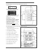
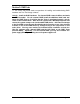
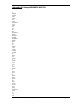
The following diagram shows the External RAID from the front view:
1. LCD Status Panel
First 6 letters on the second line correspond to
each of the HDD bays (Left to Right (1 - 6)):
O
On-line and Functional
R
Error Occurred
I Identifying Disk Drive
S Spare Disk Drive
X
Disk Drive Not Installed
Second item listed is the Raid Level (R5=Level 5).
Third item listed is SCSI ID # (ID:2=SCSI ID 2).
2. HDD Trays 1 – 6
(Hot-swappable Drive carriers)
3. Function Keys (?, ?, Enter, ESC)
(Allows navigation and selection on LCD Panel)
4. Power Supply Indicator (PWR Unit 1, PWR Unit 2)
(Green when unit is plugged in and working)
5. Host Computer Access Indicator
(Yellow when Host Computer is accessing RAID)
6. HDD Tray Lock (Lock/Unlock)
(Locked (Points Right), Unlocked (Points Up))
7. HDD Status Indicator ? ? ?
(Error (Red), Access (Yellow), Power-On (Green))
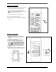
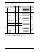
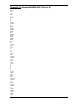
The following diagram shows the External RAID from the rear view:
1. RS232 Communication Port
(Used by Factory to program SCSI Descriptor)
2. Cooling Fans (Hot-swappable)
3. Power Supply Switch (1/0 : On/Off)
4. AC Voltage Select Switch (115V/230V)
5. Power Supply Unit Switch (On/Off)
6. Power Supply Unit 1 (Upper, Hot-swappable)
7. Power Supply Unit 2 (Lower, Hot-swappable)
8. SCSI Connector to Host Computer (use one)
9. Fan Door Screws (allows access to fans)
10. Power Supply Unit 1 LED Indicator (Green)
11. Power Supply Failure Indicator (Red)
12. Power Supply Alarm Reset Switch
13. AC Power Input Socket
DocSTAR RAID
OOOOOS R5 ID:2