
Installation Instructions


8 of 8
Patent pending and/or patent
www.assaabloydss.com/patents
Copyright © 2020, Hanchett Entry Systems, Inc., an
ASSA ABLOY Group company. All rights reserved.
Reproduction in whole or in part without the
express written permission of Hanchett Entry
Systems, Inc. is prohibited. 80-0180-107_1
adamsrite.com | 800 626 7590
techsupport.adamsrite@assaabloy.com
10027 S. 51st Street, Ste. 102 Phoenix,
AZ 85044 USA
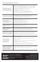
Troubleshooting Guide
The exit device doesn’t
unlock when connected to
the access control system.
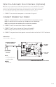
1. ENSURE that the MAIN POWER and FIRE LEDs are on. If not, check AC power
and the fire alarm interface or fire alarm jumper. If operating on battery
power, make sure the BATTERY BACKUP connector is properly seated.
2. ENSURE that switch SW2 (located next to transformer
connector J5) is set to 115 VAC.
3. DISCONNECT access control from IN1 and IN2 and place a
jumper wire at either IN1 or IN2. Set DIP-switch 1 on SW1 to ON.
If the exit devices operate, check the access controller.
No power to the exit device
ENSURE that the power connector at the exit device is properly
seated and that all wiring from the power supply to the exit
is continuous and without short-circuits to ground.
Neither exit device
retracts after the control
switch is activated
1. ENSURE that the exit device wires are securely
clamped at the PS-EXIT terminal block.
2. ENSURE continuity through power transfer devices,
such as wired hinges and door cords/loops.
Main Power LED (Red)
is not lit
1. ENSURE that AC line voltage is present.
2. ENSURE that the Primary Voltage Selection Switch (SW2) is properly set.
FIRE LED on PS-EXIT
Board is not lit
ENSURE that there is a fire alarm interface connected between
J3-9 and J3-10 or that the factory-installed jumper is in place.
IN1/IN2 LEDs do not light in
response to input switches
1. CHECK to see if an open connection in the field wiring exists between
the PS-EXIT and the control switch used to activate the exit device.
2. CHECK if there is a defective control switch on J3-1 and J3-2 or J3-3 and J3-4.
OUT1/OUT2 LEDs do
not light in response
to input switches
1. Replace PS-EXIT PCBA.
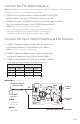
2. If one exit device works and one does not, perform the following:
• PROP the door open.
• CONNECT a voltmeter across the power leads coming from the exit device.
• ACTIVATE the non-operational exit device.
• If the voltmeter measures approximately 24 VDC at the time of
activation and the device did not retract, replace the exit device.
Exit devices retract even
though the control switch
had not been activated
VERIFY that the controlling switch is in the open position.