
Installation Instructions


7 of 8
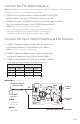
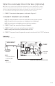
TO LINEAR
MOTOR
TO POSITION
SENSOR
GREEN WIRE CONNECTED TO LINEAR MOTOR
GREEN WIRE CONNECTED
TO EARTH GROUND
2 BLUE WIRES
TO AUTO DOOR
OPERATOR
J3
BLUE
• (J3-3) Relay Common
• (J3-4) Relay N.O.
GREEN
• Ground Wire
Wire the Automatic Door Interface (Optional)
NOTE: This step is required to use PS-EXIT with an automatic door opener. Automatic door-opening
systems need an indication of the latched state. The latch controller, located in the panic bar device,
has relay contacts that signal the latched state to the automatic door opener. The relay contacts
are closed when the latch is fully retracted and are open when the latch is extended.
1 CONNECT the automatic door opener as indicated in Diagram 6.
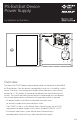
CONNECT PRIMARY (AC) POWER
NOTE 1: An earth ground must be connected to the PS-EXIT enclosure and to the push bar.
NOTE 2: Terminal block J4 accommodates up to 12 AWG wire for the 115 VAC input.
NOTE 3: A circuit breaker rated at 20 A must be provided for the installation.
2 CONNECT the AC line wire to the J4 terminal labeled L.
3 CONNECT the AC neutral wire to the J4 terminal labeled N.
NOTE: An earth ground connection is provided inside the enclosure.
4 CONNECT the ground wire to the ground screw on the back wall of the PS-EXIT enclosure.
DIAGRAM 6:
Automatic Door Operator