
Installation Instructions


6 of 8
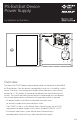
Mount the PS-EXIT power supply
1 MOUNT the PS-EXIT power supply close to the exit device (door) to be operated.
For UL 294 compliance, PS-EXIT must be installed in a controlled/protected area.
NOTES: Mounting holes are 1/4" in diameter. Enclosure dimensions are 10" x 10" x 4".
2 FASTEN the PS-EXIT power supply securely to the wall using the
mounting holes located on the back of the enclosure.
INSTALL THE BATTERY BACKUP SYSTEM (BBK-EXIT)
3 ORDER the BBK-EXIT Battery Backup System Kit and two 12 V, 7 AH batteries (EverOn EVA12-7.5F
or equivalent). Install the BBK-EXIT along with the batteries in the PS-EXIT enclosure.
NOTE: Mounting studs are provided in the PS-EXIT enclosure for the battery-backup circuit board.
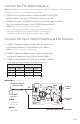
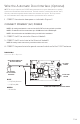
4 INSTALL the Battery Backup System circuit board in the enclosure as illustrated in Diagram 5.
NOTE: The Adams Rite Battery Backup System circuit board has a short
wiring harness to connect to the PS-EXIT circuit board.
5 PLUG the orange connector of the wiring harness into the BATTERY
BACKUP connector (J1) of the PS-EXIT circuit board.
6 CONNECT the red (+) and black (–) wires from terminal block BATT1 on the BBK-EXIT
circuit board to the positive and negative terminals, respectively, of the first battery.
7 CONNECT the red (+) and black (–) wires from terminal block BATT2 on the BBK-EXIT
circuit board to the positive and negative terminals, respectively, of the second battery.
BATTERY LOCATIONS
BATTERY BACKUP
SYSTEM CURCUIT BOARD
BATTERY BACKUP
CONNECTOR
AC INDICATOR
DIAGRAM 5:
Battery Backup Location