
Installation Instructions
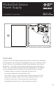


5 of 8
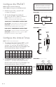
Connect the Fire Alarm Interface
NOTES: If used with fire doors, PS-EXIT is required to be under the control of an automatic fire alarm control system.
PS-EXIT is factory preset to be used without a fire alarm interface.
1 ENSURE that the installed jumper is in place at Positions 9 and 10 (FIRE)
of Terminal Block J3 to use PS-EXIT without a fire alarm interface.
2 REMOVE the jumper and CONNECT the normally-closed relay contacts of the
fire alarm interface to Positions 9 and 10 (FIRE) of Terminal Block J3.
NOTES: Closed relay contacts indicate no alarm condition.
In the event of a fire alarm, the exit devices immediately latch secure. Exit devices
remain latched during a fire alarm but always allow free mechanical egress.
The maximum current through the fire alarm contacts is 10 mA at 24 VDC.
Connect the Input Control Switches & Exit Devices
3 CONNECT the normally-open activation switch (dry contacts) for
Exit Device #1 to terminals 3 and 4 (IN1) on Terminal Block J3.
NOTE: The exit device is rated for continuous duty.
4 CONNECT the normally-open activation switch (dry contacts) for
Exit Device #2 to terminals 1 and 2 (IN2) on Terminal Block J3.
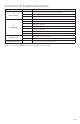
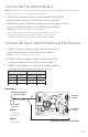
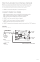
5 CONNECT the exit devices to PS-EXIT with wire lengths specified
in the table. Exit device wiring is illustrated in Diagram 4.
MLR LR
CABLE
LENGTH FT
WIRE GAUGE
AWG
CABLE
LENGTH FT
WIRE GAUGE
AWG
0 – 300 18 0 – 40 16
300 – 600 16 40 – 60 14
600 – 900 14 60 – 100 12
TO LINEAR
MOTOR
TO POSITION
SENSOR
GREEN WIRE CONNECTED TO LINEAR MOTOR
GREEN WIRE CONNECTED
TO EARTH GROUND
2 BLACK WIRES
TO PS-EXIT
J3
BLACK
• (J3-1) Power
• (J3-2) Power
GREEN
• Ground Wire
DIAGRAM 4: Exit Device Wiring