
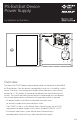
Installation Instructions


4 of 8
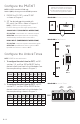
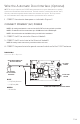
Configure the PS-EXIT
NOTE: PS-EXIT is rated for 115 VAC only.
Switch 2 (SW2) is factory preset for 115 VAC operation.
1 ENSURE that PS-EXIT is set to 115 VAC
as shown in Diagram 1.
2 SET the desired operating mode with
DIP-switch 1 on SW1 as shown in Diagram 2.
NOTE: PS-EXIT has two operating modes.
PS-EXIT is factory-preset for single-input operation.
SINGLE INPUT (SEQUENTIAL OPERATION)
APPLICATION: control double-door exit with one input.
OPERATION: either input retracts the corresponding
exit followed by retraction of the second device.
DUAL INPUT (INDEPENDENT OPERATION)
APPLICATION: control two separate exits with two inputs.
OPERATION: Input IN1 retracts device connect to OUT1.
Input IN2 retracts device connect to OUT2.
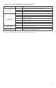
Configure the Unlock Times
NOTE: PS-EXIT has two unlock timers.
1 To configure the unlock time for OUT1, set DIP-
switches 3, 4, and 5 on SW1 to ON/OFF for the
desired unlock time listed in the table below. See
the example settings shown in Diagram 3.
DIP
SWITCH
2
SEC
5
SEC
10
SEC
15
SEC
20
SEC
30
SEC
45
SEC
60
SEC
3 OFF ON OFF ON OFF ON OFF ON
4 OFF OFF ON ON OFF OFF ON ON
5 OFF OFF OFF OFF ON ON ON ON
2 To configure the unlock time for OUT2, set DIP-
switches 6, 7, and 8 on SW1 to ON/OFF for the
desired unlock time listed in the table below. See
the example settings shown in Diagram 3.
DIP
SWITCH
2
SEC
5
SEC
10
SEC
15
SEC
20
SEC
30
SEC
45
SEC
60
SEC
6 OFF ON OFF ON OFF ON OFF ON
7 OFF OFF ON ON OFF OFF ON ON
8 OFF OFF OFF OFF ON ON ON ON
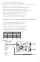
CAUTION
Damage to the PS-EXIT or to exit devices
may occur if connections are not made in
accordance with the following procedure, or
if connections are bypassed or omitted.
J4
115 V
L N
230 V
SW2
ON
ON
SINGLE
INPUT
DUAL
INPUT
ON
1 2
OFF
SW1
ON
EXIT
DEVICE
#
1
EXIT
DEVICE
#
2
1 2 3 4 5 6 7 8
DIAGRAM 1: Primary Voltage Setting
DIAGRAM 2: Dip Switch 1
DIAGRAM 3: Unlock Times