
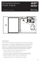
Installation Instructions


3 of 8
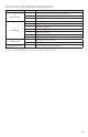
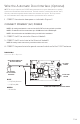
Connector & Signal Descriptions
CONNECTOR PIN DESCRIPTION
J1
Battery Backup
1 24-V (+) from battery charging system during AC fail
2 24VDC supplied to battery charging system
3 24-V return
J3
Field Wiring
1 & 2 Input #2, normally-open activation switch input
3 & 4 Input #1, normally-open activation switch input
5 Exit Device #2 return
6 Exit Device #2, +24 VDC when activated
7 Exit Device #1 return
8 Exit Device #1, +24 VDC when activated
9 & 10 Fire alarm interface, normally-closed (no alarm) input
J4 Main Power
L Main (AC) power live/hot input
N Main (AC) power neutral/return input
Safety ground screw Connection point for AC safety ground
NOTES: Fuse F2 is not user-serviceable. If replacement is needed, it must be returned to
the factory. The maximum RMS input current to the PS-EXIT is 0.70 A at 115 VAC.