
Spec Sheet

1870 Series Flushbolt
©2008 ADAMS RITE MANUFACTURING CO.
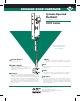
DIMENSIONS
INSTALLATION
Nominal, subject to tolerance extremes.
INCHES
MILLIMETERS
Basic lock mechanism boxed with actuator arm attached,
rod/bolt assembly unattached. Stainless steel bolt guide,
mounting screws and installation instructions included.
Cylinders available at extra cost. Shipping weight: 1-1/4 lbs.
STANDARD PACKAGE
BACKSET “A”
ARMORED
FACEPLATE
1“ x 6-7/8”
31/32“
24.6
1-1/8“
28.6
FLAT 1870
RADIUS 1871
LH BEVEL 1872-05
RH BEVEL 1872-06
RADIUS w/WEATHERSTRIP
1871W
1.63
41.4
1.78
45.2
HOW TO ORDER
Backset
2
3
31/32“
1-1/8“
Handing
LH or RHR
RH or LHR
Non-Handed*
5
6
0
Faceplate Shape
1870
1871
1872
1871W
Flat
Radius
Bevel
Radius w/strip
1871 - 20 - 628
Specify quantity and the following information.
Order related hardware separately.
Finish
628
313
335
Clear Anodized
Dark Bronze Anod.
Black Anodized
*Any flat or radius face.
.88
22.3
"A"
C
L
1.0
25.4
BACKSET MEASURED
AT CENTERLINE OF
STILE NOSE
.25
6.3
6.38
162.0
6.87
174.6
.69
17.5
THROW
1.34
34.0
6.00
152.0
12.00*
304.0
*STANDARD LENGTH
OTHER LENGTHS AVAILABLE
ON SPECIAL ORDER
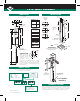
Lock & Cylinder
Installation
Stile
Preparation
FOR INSTALLATION LOCKING THRESHOLD
INVERT FOR HEADER LOCKING
BOLT
C
L
.50
12.7
DIA.
.87
22.2
1.594
40.4
1.01
25.6
6.885
174.8
1.25
31.7
DRILL & C'SK
FOR #10-32
FLAT HEAD SCREWS
DIA.
.156
3.9
R
(4 PLCS)
THRESHOLD
.68
17.4
.562
14.2
12.00
304.0
.57
14.6
L
C
STILE
CUTOUT
TOLERANCE:
+ .015
_
.000
+ 0.38
_
0.0
1870 Series locks
are operable by any
standard 1-5/32“
diameter mortise
c y l i n d e r w i t h
®
special MS cam dimensioned as shown.
®
Cylinders with MS cams can be readily
obtained from most cylinder manufacturers.
See page SW-33 for cylinder make and trim
ring information.
Cylinder Cam
CYLINDER
C
L
.182
4.62
.800
20.32
.120 R
3.05
CAM
TOLERANCE:
+
_
.005
+
_
.13
CYLINDER
HOW BACKSET
IS MEASURED:
C
L
C
L
FLAT
RADIUS
BEVEL
C
L
C
L
NOTE:
MACHINE SCREWS
ARE FURNISHED.
FOR SECURITY, INSTALL
BOLT GUIDE FROM
INTERIOR OF DOOR.