Adams Arms Micro, and Micro Adjustable Kit Installation Parts required 1. 2. 3. 4. 5.
Receiver Bushing install 1. The first step to installing your kit is to install the receiver bushing into the back of the gas tube channel inside the upper receiver. You may want to hand-tighten a flash hider to the end of your barrel to prevent damage to the threads during this step. 2. The receiver bushing has a tapered end and a flat end. Place the bushing onto the dowel tool, with the tapered end facing out, and the flat side resting on the dowel.
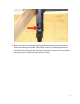
4. When you have the bushing lined up with the opening, use a hammer to knock the bushing into place. When fully in place, the bushing should be just below the surface of the opening. Sometimes this will be a very tight fit and may require significant force to put in place.
If the bushing is not tight, or just falls into place, remove the bushing and apply red loc-tite to the outside of the bushing and re-insert.
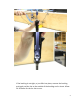
Once you have the receiver bushing installed, you will need to check to verify that the barrel nut is aligned correctly. 1. The barrel nut needs to be tightened and aligned so that a notch in the barrel nut is perfectly aligned with the opening in the upper receiver for the drive rod Note – picture shown with barrel removed for clarity 2.
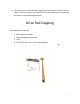
• The barrel nut must be perfectly aligned to ensure proper function of the upper. If the barrel nut is not centered it will put pressure on the drive rod and cause it to bind during operation Drive Rod Gapping Tools/equipment required 1. 2. 3. 4.
Assembly Once the receiver bushing is in place, you are ready to install the rest of the piston kit. The Adams Arms piston system is designed to have a gap built into it between the striking face of drive rod, and piston key of the carrier. The spec for this gap is .015 - .025 inches. This gap has multiple important functional purposes. It allows for a slight amount of heat growth in the drive rod.
1. If your bolt has gas ring on it, you will need to remove the gas rings, and install the included bolt spring 2. Slide the spring onto the striking end of the drive rod.
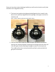
3. The drive rod bushing has a flat side, and a recessed side. 4. Slide the recessed side onto the striking end of the drive rod. Once it has reached the spring, push down on the bushing and twist, compressing the spring and locking the bushing and spring together 5. Your kit will include either an adjustable or non adjustable block. The adjustable block has a teardrop shaped selector on the front of the gas block. The non Adjustable has a smooth face.
6. Remove the gas selector from the gas block. (Adjustable Block Only) The selector is removed by rotating the selector to the right, or left while applying rearward pressure, until the selector slides free.
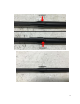
7. Place the drive rod onto the gas block and slide it onto the barrel 8. Position the gas block so it sits between .026 - .035 off the shoulder of the barrel. Using two business cards to space the gap. This will give you a good starting point for setting the correct gap. 9.
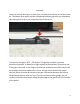
in position. Tighten one of the set screws, enough to hold the block in place, but not enough to prevent you from repositioning the block with light hammer taps. 10. Insert the bolt carrier group into the upper. With one hand, grasp the upper receiver, holding the bolt carrier group in battery with your thumb, and stand the assembly up with the muzzle resting on the table. 11.
12.Use your feeler gauge to measure the space between the back of the gas block and drive rod cup, ensuring that the space is between .015 and 0.25. A standard business card is about .011. if you do not have a feeler gauge you can use two business cards pressed tight together.
If the gap is larger than .025, use light hammer taps on the face of the gas block, to move the gas block backwards and close the gap. If the gap is less than .015, use light hammer taps on the back of the gas block to move it forward and increase the gap size. After making adjustments, re-measure with the gapping tool. Repeat process as necessary until the gap is correct.
13. Remove the bolt carrier group Section 3 Gas Block Alignment Tools/equipment required 1. Plastic or Nylon hammer Assembly Gas block alignment is crucial for several reasons. First, it helps ensure that the gas block is completely covering the gas port in the barrel. Second, in the same way that a barrel nut that is not properly aligned will cause the drive rod to bind, a crooked gas block will also cause drive rod binding.
1. The first step in aligning the gas block has already been taken during the gapping process, when the upper was laid on the table and the set screw is tightened while putting downward pressure on the barrel. As long as this was done on a level surface, it creates a good starting point. Look down the top of the upper receiver over the top of the gas block to see if it is visually canted to one side or the other. 2.
in the 360 degrees which a drive rod can rotate, that allows the drive rod to drop freely, it is passable. 4. Once the gas block is properly aligned, tighten all the set screws to the appropriate torque spec of 87 Inch-lbs 5. Once the screws are tight, re-check the drive rod gap. 6. (Adjustable only) Once the piston kit is completely installed on the upper, reinstall the gas selector.
Section 4 Gas Adjustments The Adjustable block has 5 positions, starting at full gas with the selector all way to the left, to 11% open on the last position.