
Product Manual


6
Adam Equipment Company Ltd 2011
You should expect to see a positive voltage reading of between 0 and 2
milli volts when the load cell assembly is at no load, and when a
downward force is applied to the load cell assembly the reading should
increase.
If with no load a reading of more than 2 milli volts is recorded then this
suggests damage to a load cell may have occurred and a replacement
load cell is required.
As there are 4 x load cells each one should be measured individually at
it’s connection point on the OCL PCB so as to determine which cell or
cells are faulty.
For products without an OCL PCB the same measurements can be taken
at the base connector point where the 4 x load cell connections are
joined.
To measure the signal output from each load cell accurately you will
have to de solder at this point each set of signal wires relevant to the
cell that you measure.
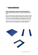
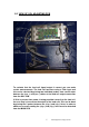
Please note where sense wires are present that these should always be
connected with the matching excitation wire as shown in the picture
When replacing a load cell the correct type and capacity load cell should
be selected, once fitted the scale will need to be calibrated and checked.
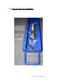
To replace a load cell, firstly remove the 2 x hex bolts that fix the load
cell in place and de solder or disconnect the wires of that load cell.
Fit the new load cell ensuring that the arrow for direction of movement
points towards the surface of the structure as the picture above shows,
tighten well and then connect the wires.
Where an OCL adjusting PCB is present you should ensure that the new
load cell is weighing correctly and matched to the other load cells by
adjusting the potentiometer on the PCB that is relevant to that load cell,
each potentiometer is marked to relate to a particular load cell.
This is done by placing a weight over the corner of the base where the
new load cell has been fitted, a reading is taken and compared against a
reading from another corner weighing, adjust the output of the new load
cell fitted using the potentiometer for that load cell until the reading for
this corner matches all other corners, the base can then be recalibrated
correctly
6.0 LOAD CELL REPLACEMENT