
Product Manual


5
Adam Equipment Company Ltd 2011
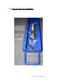
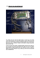
5.0 VIEW OF OCL ADJUSTING PCB
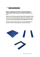
To evaluate that the load cell signal output is correct you can make
certain measurements. The load cell functions using a 5Vdc input and
this can be checked by placing two individual probes from a multi meter
between the (exc +) and (exc-) cables at the load cell output connection
from the OCL PCB.
If 5Vdc is present then power is being provided correctly to the load cell,
the next step is to measure the output of the load cells, this can be done
by placing the 2 probes between the (sig +) and (sig -) wires. In order to
obtain an accurate reading the (sig +) and (sig -) wires must be detached
from the MAIN PCB.