Adam Equipment PT LP PU Service Manual Part No- 700660173 – revA September 2011 Adam Equipment Company Ltd 2011
CONTENTS 1.0 2.0 3.0 4.0 5.0 6.0 7.0 8.0 9.0 PRODUCT DESCRIPTION ………………………………… 2 SPECIFICATION TABLE …………………………………… 3 TROUBLE SHOOTING TABLE ……………………………. 3 VIEW OF LOAD CELL ASSEMBLY ………………………. 4 VIEW OF OCL ADJUSTING PCB …………………………. 5 LOAD CELL REPLACEMENT ……………………………… 6 BASE TO INDICATOR CABLE CONNECTIONS ………… 7 PARTS LIST …………………………………………………..
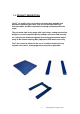
1.0 PRODUCT DESCRIPTION The PT, LP and PU series of products are heavy duty portable and permanent platform type scales, they all use the same load cells, Indicator cables and base connectors ensuring conformity within the range. They are made from heavy gauge mild steel using a strong construction design to ensure maximum capacity readings are correct and accurate. 4 x Load cells are fitted and adjusted for exacting and matched output using an Off Centre Loading (OCL) adjustment PCB where necessary.
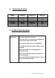
2.0 SPECIFICATION TABLE MODEL CAPACITY LOAD CELL OCL PCB PT 1000 PT 2000 PT 3000 LP 1000 LP 2000 PU 1500 PU 3000 1000kg 2000kg 3000kg 1000kg 2000kg 1500kg 3000kg 1000kg x 4 1000kg x 4 2000kg x 4 1000kg x 4 1000kg x 4 1000kg x 4 2000kg x 4 YES YES YES NO NO YES YES 3.
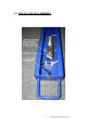
4.
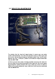
5.0 VIEW OF OCL ADJUSTING PCB To evaluate that the load cell signal output is correct you can make certain measurements. The load cell functions using a 5Vdc input and this can be checked by placing two individual probes from a multi meter between the (exc +) and (exc-) cables at the load cell output connection from the OCL PCB.
You should expect to see a positive voltage reading of between 0 and 2 milli volts when the load cell assembly is at no load, and when a downward force is applied to the load cell assembly the reading should increase. If with no load a reading of more than 2 milli volts is recorded then this suggests damage to a load cell may have occurred and a replacement load cell is required.
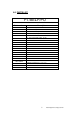
7.0 BASE TO INDICATOR CABLE CONNECTIONS All base to Indicator cables are 7 core and wired following the pin numbers as below.
8.0 PARTS LIST PT/AELP/PU Part number Description 7.00.1.0.0226 LOAD CELL 1000kg- SQB 7.00.1.0.0227 LOAD CELL 2000kg - SQB 7.00.1.0.0178 LOAD CELL S/S 1000kg - BM8H 7.00.1.0.0179 LOAD CELL S/S 2000kg - BM8H 7.00.4.0.0040 PT/ AEPU INDICATOR CABLE - GK 7.00.4.0.0054 PT/ AEPU INDICATOR CABLE - AE 402 7.00.4.0.0062 AELP INDICATOR CABLE - GK 7.00.4.0.0063 AELP INDICATOR CABLE -AE 402 7.00.4.0.0038 SUMMING ECL PCB 7.00.1.0.0151 BASE CONNECTOR 7.00.2.0.
9.0 WARRANTY INFORMATION Adam Equipment offers Limited Warranty (Parts and Labour) for the components failed due to defects in materials or workmanship. Warranty starts from the date of delivery. During the warranty period, should any repairs be necessary, the purchaser must inform its supplier or Adam Equipment Company. The company or its authorised Technician reserves the right to repair or replace the components at any of its workshops depending on the severity of the problems.
Manufacturer’s Declaration of Conformity This product has been manufactured in accordance with the harmonised European standards, following the provisions of the below stated directives: Electro Magnetic Compatibility Directive 2004/108/EC Low Voltage Directive 2006/95/EC Adam Equipment Co. Ltd. Bond Avenue, Denbigh East Milton Keynes, MK1 1SW United Kingdom FCC COMPLIANCE This equipment has been tested and found to comply with the limits for a Class A digital device, pursuant to Part 15 of the FCC Rules.
ADAM EQUIPMENT is an ISO 9001:2008 certified global company with more than 35 years experience in the production and sale of electronic weighing equipment. Adam products are predominantly designed for the Laboratory, Educational, Medical, retail and Industrial Segments.