
Datasheet


VCNL4000
www.vishay.com
Vishay Semiconductors
Rev. 1.6, 24-Aug-11
7
Document Number: 83798
For technical questions, contact: sensorstechsupport@vishay.com
THIS DOCUMENT IS SUBJECT TO CHANGE WITHOUT NOTICE. THE PRODUCTS DESCRIBED HEREIN AND THIS DOCUMENT
ARE SUBJECT TO SPECIFIC DISCLAIMERS, SET FORTH AT www.vishay.com/doc?91000
Register #1 Product ID Revision Register
Register address = 81h. This register contains information about product ID and product revision.
Register data value of current revision = 11h.
Register #2 without Function in Current Version
Register address = 82h.
Register #3 LED Current Setting for Proximity Mode
Register address = 83h. This register is to set the LED current value for proximity measurement.
The value is adjustable in steps of 10 mA from 0 mA to 200 mA.
This register also contains information about the used device fuse program ID.
Register #4 Ambient Light Parameter Register
Register address = 84h.
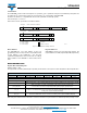
TABLE 2 - PRODUCT ID REVISION REGISTER #1
Bit 7Bit 6Bit 5Bit 4Bit 3Bit 2Bit 1Bit 0
Product ID Revision ID
Description
Product ID
Read only bits. Value = 1
Revision ID
TABLE 3 - IR LED CURRENT REGISTER #3
Bit 7Bit 6Bit 5Bit 4Bit 3Bit 2Bit 1Bit 0
Fuse prog ID IR LED current value
Description
Fuse prog ID
Read only bits.
Information about fuse program revision used for initial setup/calibration of the device.
IR LED current value
R/W bits. IR LED current = Value (dec.) x 10 mA.
Valid Range = 0 to 20d. e.g. 0 = 0 mA , 1 = 10 mA, …., 20 = 200 mA (2 = 20 mA = DEFAULT)
LED Current is limited to 200 mA for values higher as 20d.
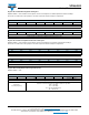
TABLE 4 - AMBIENT LIGHT PARAMETER REGISTER #4
Bit 7Bit 6Bit 5Bit 4Bit 3Bit 2Bit 1Bit 0
Cont. conv.
mode
N/A
Auto offset
compensation
Averaging function
(number of measurements per run)
Description
Bit 7
Cont. conversion mode
R/W bit. Continuous conversion mode.
Enable = 1; Disable = 0 = DEFAULT
This function can be used for performing faster ambient light measurements. Please refer to the
application information chapter 3.3 for details about this function.
Bit 3
Auto offset compensation
R/W bit. Automatic offset compensation.
Enable = 1 = DEFAULT; Disable = 0
In order to compensate a technology, package or temperature related drift of the ambient light values
there is a built in automatic offset compensation function.
With active auto offset compensation the offset value is measured before each ambient light measurement
and subtracted automatically from actual reading.
Bit 0 to bit 2
Averaging function
R/W bits. Averaging function.
Bit values sets the number of single conversions done during one measurement cycle. Result is the
average value of all conversions.
Number of conversions = 2
decimal_value
e.g. 0 = 1 conv., 1 = 2 conv, 2 = 4 conv., ….7 = 128 conv.
DEFAULT = 32 conv.